I have an instrument here that uses it. it works great actually but its not practical for a 50 Ohm source. The power requirements are too high.
An alternative is to make the source completely floating and then it doesn't matter whether one side (or the other) is grounded or not. I have another instrument like this. With a 50 Ohm output it enables very low impedance attenuators which are useful for testing high gain circuits.
Yes and all it takes is placing the output amplifier on a separate winding of the power transformer to float. Then either output can strap to main ground.
Wonderful design.
Well, well, I've been doing tests on EMU0202 USB and it would seem the DAC and ADC's noise floor depends on signal level, and quite a bit. Check out the graphs and explanations in this post :
http://www.diyaudio.com/forums/pc-based/302493-test-bench-e-mu-0202-usb-2.html#post4960668
If you got a prototype, and run a test signal through it I can run it through this little software I wrote so we can know if your ADC behaves the same way as mine or different. Interested ?
http://www.diyaudio.com/forums/pc-based/302493-test-bench-e-mu-0202-usb-2.html#post4960668
If you got a prototype, and run a test signal through it I can run it through this little software I wrote so we can know if your ADC behaves the same way as mine or different. Interested ?
@diyaudnot
No, there is no official GB list yet. I am still trying to work out the details. But I am determined to get there, and the order period will of course be extended beyond the initial indication.
@peufeu
Why not? The AKM converters luckily have a very flat noise floor over frequency, in contrast to what you have measured on the E-MU 202 USB. But it could still be interesting to check the noise on the Audio Analyzer.
OK!
Test signal is 128 Hz sine, full scale, looped back through DAC and ADC. Set sample rate to 192k, and record 20 seconds as format of your choice (like 24 bit or float WAV). If you send me a download link via PM I'll run it through the program. I wonder what'll come out...
Note : 128 Hz means the period is an integer number of samples, and not a multiple of 50 or 60 Hz mains.
If the sine is not perfectly synchronous to the sample rate will the measurement fail? Can we separate the DAC from the ADC this way using a stable analog oscillator? Do harmonics degrade the measurement?
I never gave it a moment's thought and use my Amber 3501A sine source with my M-Audio 24192 sound card based measurement setup habitually. I have not observed any issues, I'm not aware of any requirement that the source has to be synchronous with the acquisition hardware. (There will likely be significant and unknowable delays in analog hardware being measured?)
OK!
Test signal is 128 Hz sine, full scale, looped back through DAC and ADC. Set sample rate to 192k, and record 20 seconds as format of your choice (like 24 bit or float WAV).
Do you know a readily available program, which can generate the 128 Hz and record the input in e.g. a wav file? Using ASIO interface, to avoid resampling in Windows.
Do you know a readily available program, which can generate the 128 Hz and record the input in e.g. a wav file? Using ASIO interface, to avoid resampling in Windows.
MATAA lets you save the raw data to a file.
Do you know a readily available program, which can generate the 128 Hz and record the input in e.g. a wav file? Using ASIO interface, to avoid resampling in Windows.
Audacity
Or: The basic wav format is simple, it is not to hard to write a little program that writes the wanted wav and then you have 100% control on the content.
I use Audacity.
Set project sample rate to 192k (bottom left of screen).
Set playback & recording devices (top of screen, use WASAPI).
Menu > Generate > Tone in menu...
Then use Overdub. Set levels and record.
Tutorial - Multi-track Overdubbing - Audacity Manual
To export track, double click in it and use File > export selected audio
Have a nice day")
Set project sample rate to 192k (bottom left of screen).
Set playback & recording devices (top of screen, use WASAPI).
Menu > Generate > Tone in menu...
Then use Overdub. Set levels and record.
Tutorial - Multi-track Overdubbing - Audacity Manual
To export track, double click in it and use File > export selected audio
Have a nice day
Audacity can work with ASIO but you need to add some stuff since ASIO is not licensed the same. I can provide an accurate 128 Hz sine wave at 192 KHz from several sources. The best probably being a digital capture from the Altor generator. How long should it be? I would distribute it as a FLAC file.
I think I just managed to do it with Audacity, using WASAPI interface.
The source is not a problem. I have previously generated wav files e.g. with a 160 kHz tone and played it back with xmplay at 384 kHz. The problem was getting a way to record it, using ASIO. But it seems like WASAPI works OK, once everything has been set up correctly.
The source is not a problem. I have previously generated wav files e.g. with a 160 kHz tone and played it back with xmplay at 384 kHz. The problem was getting a way to record it, using ASIO. But it seems like WASAPI works OK, once everything has been set up correctly.
Hi
JensH, this would be a bit time consuming for you but because a lot of us use REW, would it be ok for you to show us a basic loopback measurement say at 1khz using REW generator and RTA analysis, with FFT 64k and average 32 for example, at 48khz/96 and 192k, up to you to choose the DAC and ADC dbFS which provide the best results in term of thd, and then in term of noise.
this way we would be able to "compare" to our own home equipment and feel the benefit of investing in your analyser.
Also JensH the equipment is dramatically missing a SPDIF/AES chanel... you might prototype an add-on asap and then let us know if an upgrade is doable (by us) or may be you have time to setup this as an option for ordering ?
HPW about your software, any chance you could talk with JensH together and come with a super bundle ??? your software looks very interresting and maybe you could update your interface to use the xmos api enabling the change of the input levels/relay ? also you have possibilities to aggregate channels, which might bring something in the perf right ?
Last but not least, did you guys thought about the possibility to null the fundamental by having one of the input Chanel configured in a differential mode where the minus signal comes from the second DAC ? by applying a proper FIR to this second DAC we could emulate the transfer function of the amp and then make sure the nulling is made properly. The small FIR could be held into the xmos and with some nlms on the PC host you could certainly calculate the coef by seeking for the minimum value of the fundamental
some thoughts in the morning
Last edited:
An AES output is not as important since it's easy to get decent PC-based ones [although it's pretty nifty in the AP devices to be able to easily manipulate AES bits and jitter etc.]
An AES input and buffered I2S input would be really useful to easily test e.g. ADC front-ends alone, but unless there's a series ASRC inbetween this is of course a much more difficult Change Request and solidly in the feature creep domain. Having said that, if the I2S pins of the ADC are available for those brave enough to tinker at own risk it would already be useful.
@JensH, is the ADC running as I2S master or slave?
Last edited:
For I2S and SPDIF source I suggest getting one of these: JKGEN - ALTOR AUDIO it gives you all the signals you could want or ask for anything missing. Adding SPDIF in or out would be nice however a little complex. Maybe a simple XMOS USB to I2S & SPDIF I/O module would accomplish the digital I/O goal. An integrated driver so the app can connect to different input and output combinations would be needed.
Add this and almost anything is possible: http://www.akm.com/akm/en/product/datasheet1/?partno=AK4137EQ&link_id=link679
Add this and almost anything is possible: http://www.akm.com/akm/en/product/datasheet1/?partno=AK4137EQ&link_id=link679
Last edited:
@maxidcx
I made some loop back measurements with the REW generator and RTA analysis. It was the first time that I used it, so bear with me if it is does not cover all your wishes. I measured at output levels of -20dBFS, -10dBFS and -3dBFS. For some reason the program would not let me go higher than -3dBFS.
At the high level it is clear that the distortion of the DAC increases.
Regarding the SPDIF/AES: are you looking for input, output or both?
PWatts:
Digital interfaces would be nice to have, but yes, it would be a serious feature creep. I have worked with some ideas, but at the moment I cannot make any promises. In any case it would be a long term project. I have got my hands full at the moment.
The ADC is running as an I2S slave. The XMOS device is the master, but the timing is controlled by a clean crystal oscillator, located close to the ADC and DAC.
@1audio
Yes, a good sample rate converter could solve many of the clocking issues that could come up when designing a digital interface.
Attachments
-
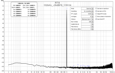 REW_1kHz_-20dBFS_192kHz_64k FFT_average 32_20dBV input_170124.png61.9 KB · Views: 556
 -
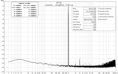 REW_1kHz_-20dBFS_192kHz_64k FFT_average 32_10dBV input_170124.png63.3 KB · Views: 548
 -
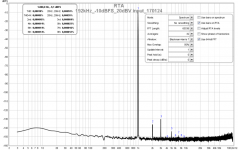 REW_1kHz_-10dBFS_192kHz_64k FFT_average 32_20dBV input_170124.png62.9 KB · Views: 544
 -
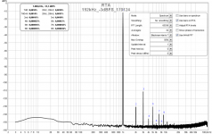 REW_1kHz_-3dBFS_192kHz_64k FFT_average 32_30dBV input_170124.png61.8 KB · Views: 540
- Home
- Design & Build
- Equipment & Tools
- DIY Audio Analyzer with AK5397/AK5394A and AK4490