thank you everyone, especially @Pyramid , for your help. It took me a long while, I move slowly. All that's left is to dial it in - the speed fluctuates. culprits are the pulley may not be attached quite right, the reduced voltage could be too high or low, the rubber belt could be twisted.
Has anyone tried adjusting the phases? If so, can you lend some insight, I don't have a grasp on what should happen as each of the phases is adjusted.


Has anyone tried adjusting the phases? If so, can you lend some insight, I don't have a grasp on what should happen as each of the phases is adjusted.
Hello,
and first off all thank you to all that made this project possible and take their time to distribute parts and support those of us in need. Really apreciate it.
I am currently in the process of finalising my SG4 controller for an Empire 208 turntable that would be otherwise useless.
Last weekend i have started it up for the first time, and to my pleasand surprise, it seemed to work just fine. Did not try it thoroughly, or play any music as the tt itself still needs a bit of work.
After trying if all the functions work as needed, i have noticed that 1 amplifier and Transformer (120°) gets hot to the touch while the others (0° and 240°) remain cool. measured voltages throughout, and until the amplifier output, all seems fine, but after the transformes, there is no ac voltage present, right before the capacitor. Have checked all the connections again, and all seems right.
Tried with and without thermosistors and the simptoms are the same. At this point i am all out of ideas, how to further troubleshoot - my experience is limited when it comes to electronics, but progressing slowly.
Anybody has an idea what i could do next, or what might cause this?

Thank you both for the feedback. Shorted winding seems the most probable cause.
I will save the time that it takes to check everything, and order a new set of xformers., A similar one is sadly impossible to find. I will transit to cased xformers, with pcb, which seem a lot more user friendly.
I also have to change the layout, as this time the things are much to cramped. I will go ahead and do it right this time.
Good morning from GREECE
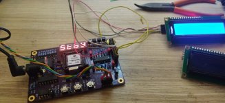
I have made 4 Phase Sinewave Generator
And the 3 phase class D motor drive amp
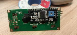
Everything works fine except the LCD interface I have the PCF-8574T version,
But I read that with the latest version 1.05 there is no problem
I have also tried the short circuit on tp1
But it doesn't display characters
What am I doing ? error
Thanks
I have made 4 Phase Sinewave Generator
And the 3 phase class D motor drive amp
Everything works fine except the LCD interface I have the PCF-8574T version,
But I read that with the latest version 1.05 there is no problem
I have also tried the short circuit on tp1
But it doesn't display characters
What am I doing ? error
Thanks
Attachments
I have just received my most recent batch of SG4 chips, I'm not saying this will be the last, but the lead time on delivery
for the chips is getting to be problematic.
Because of this I'm asking that anyone who is planning to build the SG4 controller let me know by PM and I will try to ensure availability for
as long as feasible. (I know the chips are 'available' from China but I won't go down that route; only buying from reputable suppliers.
Following up on this if there are any ideas. Will post in MA3 thread too as I am using that amp motor too. Getting worse/more frequent in the last few weeks.Got a weird issue. Built this 2+ years ago now and it has worked without fault since, except… the last month or so. Now after running for an hour or two or sitting in standby for a couple hours it slows down significantly. Also have digital tach hooked up and it will slow by 2 to 3 tenths of an rpm, whereas previously it never deviated by greater than +/- 0.02 rpm. Any ideas? Bad capacitor??
@04dgmsilv try cleaning the belt, platter, etc with alcohol. worked for me.
Hi all.
I have 2 pieces of 1.03 SG4 chips which I bought almost 2 years ago.
Now had time to put under assembly another SG4 controller.
My previous experience assembling SG4 was problems free and worked from the first time.
Now I have a problem.
Once I power up the board the lite-on display fully lights with all segments and nothing works. No reaction at all.
Measured everything I could as follows:
U2 - Pin4 - 8volts;
U3 - Pin14 - 5volts
- Pin18 - 5volts
U5 - Pin1 - 5volts
- Pin3 - 1,4volts
- Pin5 - 5volts
- Pin9 -5volts
-Pin11 - 1,4volts
- Pin13 - 1volt
- Pin14 - 5volts
U6 - 8volts
U8 - pin 5,6,8 - 5 volts
I am using DS1833 - 5. The revision of the board is not from the newest. Exchanged the DS1833 with two different ones - the same.
I have a pulsation from the reset on turning the PCB on....So the reset is working.
Another PCB prepared to the same result: all segments of the display are on and no operation possible.
Exchanged the chip with the second one- the same thing.
Exchanged the quartz as well.
What might be the problem?
Is it possible that both SG4 chips are dead? Probably bad batch or something?
Thank you in advance.
Last edited:
Another test performed:
2n7000 transistors exchanged to new ones - no change of the behavior.
Changed again DS1833-5 with another (3rd) one - the same.
The input to U4 is 5VDC and the output going to pin 10 of the uP is 4.75VDC for ~350mS at power up then drops to zero. So this means the DS1833 is working and is sending a reset signal to U1
I am a bit out of ideas what to try next.
Last edited:
And one final test before i lift my hands off this project for now. Back then Pyramid advised a user with a similar problem to remove the DS1833 and to substitute it temporarily with a 47nf or bigger (from Reset to 5v) cap to force the micro-controller to exit "programming" status. Did it. 47nf and then with bigger 100nf capacitor. Both tries gave no result and I am totally desperate now. What are the chances both of the chips to be faulty? They both came together.
I don't have an SG4 setup, but I'd guess to emulate the active-high power-on-reset, you'd want both a cap from VCC to the RESET input, and a bleed resistor from the RESET input to ground.
100nF/1MOhms would give a time constant of 0.1s which should be a good starting point.
100nF/1MOhms would give a time constant of 0.1s which should be a good starting point.
- Home
- Source & Line
- Analogue Source
- DIY 4 Phase Sinewave Generator for Turntable Motor Drive