New PCB for Rotary Encoder
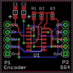
I just uploaded the PCB files to OshPark for a Rotary Encoder to SG4 interface PCB. The circuit converts the 2 quadrature signals from the encoder to a single pulse train on the UP pin when turned CW and a single pulse train on the DN pin when turned CCW. The momentary push button switch of the encoder is connected to the STBY button of the SG4. This allows all of the normal operating functions to be performed by one rotary control.
The 1 inch square board uses all surface mount components in order to keep the size down. The IC is a CD4013 in SO14 package. C1 and C2 are both 0.47uFd Tantalum caps 10V rating. R1, R2 and R3 are not necessary if you use the Arduino Rotary Encoder which has the pull up resistors already on its PCB. If you use another encoder without pull ups, add the 3 resistors (all 10K 0805 size). Vcc is connected to the 5VDC output of the regulator on the SG4.
You can order the PCB here ($5 for three):
[url]https://www.oshpark.com/shared_projects/AbsVI39H[/URL]
Attachments
Last edited:
Just ordered 3 boards and have 2 to sell at $15.64 ea (cost). Will send at cost by your preferred shipper to US. No expected delivery date yet.
PM sent - I'll take both boards. USPS Priority Mail is fine.
Pyramid
I have questions about setting the initial start up voltage. In post # 33 you state that with V.102 that the output voltage can be controlled from 0-5VPP in 128 steps. Does this mean that the start up voltage can be set at less than 5VPP, or do we still need potentiometers to attenuate the start up voltage, if one needs less than 5VPP? After reading the installation instructions, I fail to see how this is done, so assume I still need attenuators. With my amps and transformers I will need about 1.5VPP to generate about 120V on the outputs of the transformers. I see by looking at the instructions that there is a section for setting reduced voltage adjustment between 128 and 64 steps, but I assume this is the voltage drop after the 5 second delay. Is this correct?
twystd
May have posted this on the wrong forum page, so re-posted
Hi, I am a newbe to electronic circuits. But am just upgrading a Lenco 75. This controller is just what I am looking for as long as it can take the Lenco 75, 25 watt motor requirement.
Is this circuit something a Newbe could build up, on first read it seams a little complicated for me? Cheers
I am also going to use it to drive a Lenco. Provided you select an amplifier and power supply that is powerful enough, this controller will drive your 25w Lenco motor.
I think you will manage the build even if you are unexperienced. The documentation is quite good, so you will find your way. However, you must consider the fact that the finished product (including power amp, power supply and output transformer) will produce voltages that may be dangerous. Don't touch it
")
Sent fra min E5603 via Tapatalk
Pyramid
I have questions about setting the initial start up voltage. In post # 33 you state that with V.102 that the output voltage can be controlled from 0-5VPP in 128 steps. Does this mean that the start up voltage can be set at less than 5VPP, or do we still need potentiometers to attenuate the start up voltage, if one needs less than 5VPP? After reading the installation instructions, I fail to see how this is done, so assume I still need attenuators. With my amps and transformers I will need about 1.5VPP to generate about 120V on the outputs of the transformers. I see by looking at the instructions that there is a section for setting reduced voltage adjustment between 128 and 64 steps, but I assume this is the voltage drop after the 5 second delay. Is this correct?
twystd
Yes, your assumption is correct. The SG4 will ramp up from zero to 5VPP at start up in 128 steps then reduce to a level between 5VPP (128) and 2.5VPP (64). You will need to add an attenuator or change the gain of the amplifier if you need a lower voltage to drive the amplifier to full output.
I could've used the attenuator to reduce the 5VPP level at start up, but the steps sizes are fixed so if I reduced the 5VPP level to 0.75V (for some applications), that would only leave 19 steps between maximum (120V out) and zero so each step then becomes almost 6V. This could adversely affect the ramp up when exiting standby since it would now only be 19 steps of 6V which the amps may not like.
Are there folks out there that still need SG4s? This is for domestic (US) shipping only. I'd like to know how many to order for my second, and possible last batch of chips. Please let me know by posting to this thread, I'd like to order in the next couple of days. If you've already contacted me by email, to actually order chips ignore this post. BTW any response to this post won't be considered an actual order, just a guide to get an idea of how many to order, as I don't want to be stuck with a bunch of chips. If you want to actually order, please email me at twystd3 at yahoo.com. I can send you a PayPal invoice if you prefer.
twystd
twystd
Last edited:
Are these caps ok for the rotary encoder board
http://www.mouser.com/ProductDetail...=sGAEpiMZZMtZ1n0r9vR22ZBQR9LXYg3mvJYHfNO12MM=
http://www.mouser.com/ProductDetail...=sGAEpiMZZMtZ1n0r9vR22ZBQR9LXYg3mvJYHfNO12MM=
Are these caps ok for the rotary encoder board
http://www.mouser.com/ProductDetail...=sGAEpiMZZMtZ1n0r9vR22ZBQR9LXYg3mvJYHfNO12MM=
The PCB is laid out for SMT parts, so something more like this:
http://www.mouser.com/ProductDetail...=sGAEpiMZZMuEN2agSAc2pmRv4r8cj6yFk1V36MciNnk=
The caps are polarized so please observe the '+' polarity marking on the silk screen.
- Home
- Source & Line
- Analogue Source
- DIY 4 Phase Sinewave Generator for Turntable Motor Drive