 Image added
Thank you!
Thanks very much, Bill. This is just what I need. I built my first SG4 controller but the faceplate is a bit dicey looking. I'm going to order one from Front Panel Express and these dimensions will be helpful.
I did download a Gerber file viewer but still haven't been able to find how to extract the physical dimensions. I'm sure it's in there and will give me a learning exercise - even better since I now know the answers.
Thank you very much for all your efforts!
Soooo many hours of fun trying to get my front panel to look and function the way I wanted! Especially those buttons. Then you smarter guys come along with your magical gerber files and dimensioned drawings...sheesh!
Actually, I’ve come to realize that my biggest enemy seems to be the lack of accuracy in my fabrication equipment. My inexpensive mini mill and old lathe have become a thorn in my side regarding the accuracy I have needed to fabricate for this project to my expectations.
I am still struggling with what has become the final/biggest thorn, which is the pulley. If you can have it made for you in a well equipped shop pay for it. I’ve tried that route as well, and the local shop is just too busy with bigger/better jobs.
The best pulley I’ve made has had less than .001” of wobble at its end when fully engaged on the motor shaft. The problem is that at 1.5” total height it’s a little too short to engage the bottom third of my laminated platter on center the way I want it to. My table requires it to reach through the entire plinth thickness which is about 1” alone. I’m getting pretty frustrated, this has been a 9 month long resto-mod project for me.
Little problem
Hi Bill and all forum members,
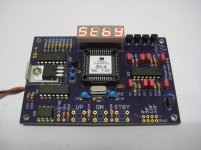
I have a little problem with a new SG4 I´ve built. I have one SG4 working perfectly with firmware version 1.02 and I built a second one (firmware 1.03) due to I wanted to place the display in the front of the panel and not attached to the PCB to make adjustments easier. I have got a Rega 24V AC motor.
The new one has not the same "force" or torque than the first one being all parameters equal and also all supporting components the same (PSU, output amplifier and turntable). It can barely (sometimes a helping hand needed) start at 33.3 rpm and it wobbles and do not reach the correct speed at 45 rpm (I have to impulse it always). The older one is perfect.
Where to look at for the problem ? Any ideas?
Another question is: I have the original (110V AC 250rpm Premotec) motor. What would you use? The 24V or the 110V one?. The main advantage of the 24V is that it´s powered directly from the output of the amplfier attached to the SG4 and the 110V need a step up transformer along with the amp to work. Nevertheless I have read somewhere in DIYAUDIO that the 110v is way better motor but I would like somekind of confirmation from the geniuses around here.
Regards.
Jorge Castellano
Hi Bill and all forum members,
I have a little problem with a new SG4 I´ve built. I have one SG4 working perfectly with firmware version 1.02 and I built a second one (firmware 1.03) due to I wanted to place the display in the front of the panel and not attached to the PCB to make adjustments easier. I have got a Rega 24V AC motor.
The new one has not the same "force" or torque than the first one being all parameters equal and also all supporting components the same (PSU, output amplifier and turntable). It can barely (sometimes a helping hand needed) start at 33.3 rpm and it wobbles and do not reach the correct speed at 45 rpm (I have to impulse it always). The older one is perfect.
Where to look at for the problem ? Any ideas?
Another question is: I have the original (110V AC 250rpm Premotec) motor. What would you use? The 24V or the 110V one?. The main advantage of the 24V is that it´s powered directly from the output of the amplfier attached to the SG4 and the 110V need a step up transformer along with the amp to work. Nevertheless I have read somewhere in DIYAUDIO that the 110v is way better motor but I would like somekind of confirmation from the geniuses around here.
Regards.
Jorge Castellano
From experience, the 24V motor is a better performance motor than 110V version which its design is to apply approximately 85V to the phases to have least vibration and decent performance for turntable use. Any lesser voltage and the motor will result with lesser torque which may affect startup. Rega installed a 3k to 12k dropper (12k for 230V input) resistor to reduce the running voltage to around 90V to maintain best compromise for torque and least vibration. Older Linn LP12 have the same 110V Premotec motor and Valhalla controller which preset the voltage at 85V. Over the decades there's been differences to implementation of the 110V motor, early ones applied over 90V to the motor and some others anything from 75V to 85V to motor. Some need a lil push to start, it was meant that way.
The 24V motor superceded the 110V motor in later Rega models as its superior and less fussy at 24Volts compared to what the 110V motor would need. The 24V Rega would have a external wall wort and phase splitter pcb fitted underneath the table.
I've tried plugging a recent Rega 24V motor model, wall wart to the speed controller and have speed control as you would with one fitted with 110V motor. No modifications needed to the Rega, just plug n play. I tested it and it worked fine, varying 33 or 45rpm.
Last edited:
Fixed...
Hi Bill and all forum members,
I have fixed it. I had installed ( from the first SG4 built) two in series resistors at the SG4 outputs of 0 and 90 to lower the output at the amp to not pass 24v at startup, but they were to high for the new board ( I guess due to different tolerances from the electronic components ). I had 80k and now I have 30k. Then when the reduced voltage jumps in the output from the amp is around 21v, I can not go lower due to the 64 value limit. Is this value any kind of technical imposition or it’s a common value 64-128?
Sorry for my English....
Regards
Jorge
You should not use a series resistance to control the output level. Use either an adjustable pot or a fixed voltage divider. The "top" of the pot (or fixed divider) will go to the SG4 output, the bottom will go to ground and the wiper (or middle of the divider) will go to the amp input. You should use a pot (or total resistance if using a fixed divider) of 10K-20K max. You can use a pot to find the correct set point that gives 24VAC, then replace that with fixed resistors of the same ratio (top of pot to wiper: bottom of pot to wiper). Example: If using a 10K pot and when adjusted to give 24VAC when the SG4 attenuator is set to max (128), the resistance from bottom of pot to wiper is 3200 Ohms, use a voltage divider with 6.8K on top and 3.3K on the bottom (values rounded to standard values).
When setup properly, the SG4 attenuator set to 128 should give you 24VAC and when set to 64 will give half that or 12VAC.
When setup properly, the SG4 attenuator set to 128 should give you 24VAC and when set to 64 will give half that or 12VAC.
Ok...I will do it...
Hi Bill,
Thanks. I appreciate.
Just for my curiosity...why can’t I use series resistors?
Regards
Jorge
You should not use a series resistance to control the output level. Use either an adjustable pot or a fixed voltage divider. The "top" of the pot (or fixed divider) will go to the SG4 output, the bottom will go to ground and the wiper (or middle of the divider) will go to the amp input. You should use a pot (or total resistance if using a fixed divider) of 10K-20K max. You can use a pot to find the correct set point that gives 24VAC, then replace that with fixed resistors of the same ratio (top of pot to wiper: bottom of pot to wiper). Example: If using a 10K pot and when adjusted to give 24VAC when the SG4 attenuator is set to max (128), the resistance from bottom of pot to wiper is 3200 Ohms, use a voltage divider with 6.8K on top and 3.3K on the bottom (values rounded to standard values).
When setup properly, the SG4 attenuator set to 128 should give you 24VAC and when set to 64 will give half that or 12VAC.
Hi Bill,
Thanks. I appreciate.
Just for my curiosity...why can’t I use series resistors?
Regards
Jorge
Just for my curiosity...why can’t I use series resistors?
Using a series resistor creates a voltage divider using the output impedance of the SG4 and the input impedance of the amp, both of which are not always constant. The input impedance includes the input caps whose impedance changes with frequency.
Ok. Understood
Thanks Bill....I appreciate.
Regards
Jorge
Using a series resistor creates a voltage divider using the output impedance of the SG4 and the input impedance of the amp, both of which are not always constant. The input impedance includes the input caps whose impedance changes with frequency.
Thanks Bill....I appreciate.
Regards
Jorge

Confused
Hi Bill,
It’s 2 AM and I am still trying to setup my SG4. I’m really confused. I am sure it’s from my ignorance in electronics.
I have used two linear 20k pot I had on hand and installed them. At the 128 value, the amp outputs around 23.71v AC but when I reduce to 64 the output only drops to around 21.50V AC.
I wired the pot ( if you see it from top) to the left ground, middle to the amp inputs and left SG4 outputs 0 and 90.
What I’m doing wrong?
Also, what is the AC and DC voltage at each SG4 output (0° & 90°) when set for 128 and 64?
Does your DVM have a frequency counter (or do you have a scope)? If so, what are the frequencies at the SG4 output (0° & 90°)?
Hi Bill, thanks for your support....
The data:
DC to amp: 24,68v
DC to SG4: 12,23v
At 128 setting and 50Hz frquency:
0º VDC 2,533v and VAC 1,793v
90º VDC 2,534v and VAC 1,793v
Amp output 23,71v AC both channels
SG4 output frequency: 50HZ at 0º and at 90º
At 64 setting and 50Hz frequency:
0º VDC 2,533v and VAC 0,8898v
90º VDC 2,534v and VAC 0,8906v
Amp output 22,41v AC left channel and 22,389 right channel.
SG4 output frequency: 50HZ at 0º and at 90º
The frequency at 67,5Hz is 67,5Hz at both settings.
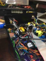
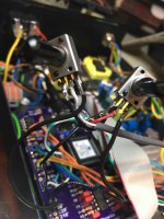
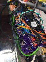
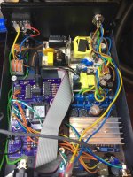
Attached are four photos, please pardon the bird nest but I'm in testing mode...I beg your pardon. Also in the photo that shows the outputs from the SG4 look dark or burnt, it is not the PCB, they are pins for testing and I will clean and tidy up with a proper cable and solder.
Regards and thanks again Bill.
Jorge
Attachments
OK, a couple of things:
Are you running this direct to a 24VAC motor without xfmr? If so, they cannot share a common return; each winding will connect to each channel of the amp.
With a 24VDC supply, you cannot get 24VAC output, even in bridge (BTL) mode. The maximum undistorted AC waveform you can expect to see is ~17VAC. The output of the amp can only produce a 24VPP signal with a 24VDC supply. Because the amp is BTL, the effective voltage is doubled or 48VPP. The RMS voltage will be 48/2.828 or 16.97VAC. 24VAC is ~68VPP. To generate 24VAC in bridge mode will require an amp that can tolerate 35VDC supply.
If you are reading 24VAC at the output of the amp, the output is most likely squarewaves or severely distorted. This is probably why the output does not drop when the SG4 output drops in half (as it does from 1.793 to 0.89VAC); the waveform is still mostly distorted and you see a slight drop in RMS value at the output, but the amp is being severely overdriven.
If you adjust the pot between the SG4 and the amp for 17VAC at 128 setting, then the voltage should drop in half to 8.5VAC at 64.
I’m lost....
Ok Bill, thanks.
The outputs of the amp drives each winding separately. No problem there.
Looking for a solution, what should I do or buy? Bigger PSU for amp or other type of amp? Both? I’m afraid I’m a little bit lost....
Sorry for all the fuss,
Regards,
Jorge
OK, a couple of things:
Are you running this direct to a 24VAC motor without xfmr? If so, they cannot share a common return; each winding will connect to each channel of the amp.
With a 24VDC supply, you cannot get 24VAC output, even in bridge (BTL) mode. The maximum undistorted AC waveform you can expect to see is ~17VAC. The output of the amp can only produce a 24VPP signal with a 24VDC supply. Because the amp is BTL, the effective voltage is doubled or 48VPP. The RMS voltage will be 48/2.828 or 16.97VAC. 24VAC is ~68VPP. To generate 24VAC in bridge mode will require an amp that can tolerate 35VDC supply.
If you are reading 24VAC at the output of the amp, the output is most likely squarewaves or severely distorted. This is probably why the output does not drop when the SG4 output drops in half (as it does from 1.793 to 0.89VAC); the waveform is still mostly distorted and you see a slight drop in RMS value at the output, but the amp is being severely overdriven.
If you adjust the pot between the SG4 and the amp for 17VAC at 128 setting, then the voltage should drop in half to 8.5VAC at 64.
Ok Bill, thanks.
The outputs of the amp drives each winding separately. No problem there.
Looking for a solution, what should I do or buy? Bigger PSU for amp or other type of amp? Both? I’m afraid I’m a little bit lost....
Sorry for all the fuss,
Regards,
Jorge
- Home
- Source & Line
- Analogue Source
- DIY 4 Phase Sinewave Generator for Turntable Motor Drive