There is a jumper on the board to accommodate both 50 and 60 Hz operation. Details in the manual pdf at beginning of thread....doh to slow. Will cover up with a semi-money shot...hope to be spinning with it by the weekend.
Attachments
Last edited:
There is a jumper on the board to accommodate both 50 and 60 Hz operation. Details in the manual pdf at beginning of thread.
Thx! I am in the US next month and will be ordering a couple of chips... Wantend to make sure that they will produce nice sinewaves on this site of the ocean too!
")
Marc
I’m not saying there is a problem. Just did not use such PCBs yet and I thought I made mistake during ordering. Thanks for relieve one’s feeling. Can you please direct me to hole effect board BOM? Digi-Key P/N preferred. Tremendously appreciate forum members prompt responses. You guys awesome.
Can you please direct me to hole effect board BOM? Digi-Key P/N preferred.
What's hole effect? Is it the Hall effect sensor kit for the Arduino or RoadRunner tachometer?
Are you referring to this? OSH Park ~
Last edited:
What's hole effect? Is it the Hall effect sensor kit for the Arduino or RoadRunner tachometer?
Are you referring to this? OSH Park ~
Sorry for confusion about Hall Effect. It is my iPhone autocorrection error. Thanks for the info. This is exactly what I looked for.
OshPark offers 1.6mm PCBs by default unless you order 2 Oz copper option, then they are 0.8mm. The PCB thickness is not specified in any of the files I provided.
The O/P of each thread has a link to purchase the parts as a shared cart from Mouser Electronics.
This is precisely what happened and didn’t connect Cu weight to PCB thickness. They might got price locked (BTW, it is almost free for US located PCB manufacture) and play is one option against the other. I’m sure I’ll be fine with 0.8mm thickness with such low voltage and current devices. Thank you a lot.
Hi Bill,
Just for your info when I mounted the SG-4 pcb, I had a little issue when mounting the pcb for the 1st time.
I felt the 4 corner mount holes are too small. I had to drill them slightly bigger to fit the commonly available M3 thread size brass standoffs which is very easy to buy here. Its the same kind used for PC motherboards. The screws I used are also exactly the same type for PC. The existing holes are less than M3.
Roadrunner Integration
Hi Bill
Sorry if this question is a little off topic, I couldn’t find another place to ask.
I’m working on some last OCD details on my turntable project that I’m using the SG4 based drive system with that I built.
Since I integrated my Roadrunner in the same case to keep things compact and clean I also decided I didn’t want the wiring for the Roadrunner sensor hanging off the side of the table.
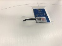
To that end, I removed the bulky stereo jack on the Roadrunner sensor pcb and the elbow plug from the sensor cable. I soldered the cable wiring directly to the sensor pcb and bonded/potted the end to the board with epoxy to seal and stabilize it.
The result gave me a height less than half of the original connection that would be easier to tuck completely under the platter out of sight where the wiring can be passed through the plinth.
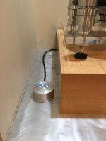
I then machined a recess and hole in the plinth for the sensor and wiring (picture).
I just need to mount the sensor with the wire passing hidden through the plinth.
I need to make sure I have a viable distance between the sensor and the magnet. I checked the manual and looked for threads/info, but couldn’t find a specification.
I’ve got a small gap of less than 2 mm between the bottom of the platter and the plinth surface. The top surface of the sensor is about 2 mm below the plinth surface without adhesive in place. So I’m guessing a gap of about 3 mm give or take.
I may have to adjust the height of the platter during setup. I’m pretty sure I’m currently within the proper gap range for proper sensor operation. Can you give me a ballpark figure on what the maximum gap can be and still have proper operation?
Hi Bill
Sorry if this question is a little off topic, I couldn’t find another place to ask.
I’m working on some last OCD details on my turntable project that I’m using the SG4 based drive system with that I built.
Since I integrated my Roadrunner in the same case to keep things compact and clean I also decided I didn’t want the wiring for the Roadrunner sensor hanging off the side of the table.
To that end, I removed the bulky stereo jack on the Roadrunner sensor pcb and the elbow plug from the sensor cable. I soldered the cable wiring directly to the sensor pcb and bonded/potted the end to the board with epoxy to seal and stabilize it.
The result gave me a height less than half of the original connection that would be easier to tuck completely under the platter out of sight where the wiring can be passed through the plinth.
I then machined a recess and hole in the plinth for the sensor and wiring (picture).
I just need to mount the sensor with the wire passing hidden through the plinth.
I need to make sure I have a viable distance between the sensor and the magnet. I checked the manual and looked for threads/info, but couldn’t find a specification.
I’ve got a small gap of less than 2 mm between the bottom of the platter and the plinth surface. The top surface of the sensor is about 2 mm below the plinth surface without adhesive in place. So I’m guessing a gap of about 3 mm give or take.
I may have to adjust the height of the platter during setup. I’m pretty sure I’m currently within the proper gap range for proper sensor operation. Can you give me a ballpark figure on what the maximum gap can be and still have proper operation?
Attachments
I used a 13mm X 2mm disc type neodymium magnet and it would work at somewhere half inch to 3/4" gap. I wonder if narrowing the gap would have any effect on the accuracy or stability in theory? I did experiment a little and didn't see anything significant, unless its entirely out with no reading.
Thanks for the response. I have the smaller neo magnet to work with right now. It is about 1.25mm thick if I remember correctly, and the gap between the plinth surface and the bottom of the platter allows it to fit with about .5mm of clearance.
The only issue I foresee is if the platter is slightly too low to clear the sensor pcb wiring which is just proud of the plinth surface. I think it will clear, but if it doesn’t I will have to shim the bearing which will add another 2mm or so to the gap. That will put me in the 5mm gap ballpark, which should still work well I hope.
The only issue I foresee is if the platter is slightly too low to clear the sensor pcb wiring which is just proud of the plinth surface. I think it will clear, but if it doesn’t I will have to shim the bearing which will add another 2mm or so to the gap. That will put me in the 5mm gap ballpark, which should still work well I hope.
Was just thinking about the rotary encoder switch function. I'm toying to mount a good quality soft press momentary switch separately on the front panel for standby/on button. I prefer a softer feel press button than the encoder push switch, won't cost much. Perhaps the 33/45 toggle too.
Was just thinking about the rotary encoder switch function. I'm toying to mount a good quality soft press momentary switch separately on the front panel for standby/on button. I prefer a softer feel press button than the encoder push switch, won't cost much. Perhaps the 33/45 toggle too.
Interesting,
I would like to see what you come up with.
I made a remote stby & speed selector switch for mine that is near the turntable. I tend not to make speed adjustments once they're set so this works fine. I'm making a smaller version with micro buttons and will machine buttons to work with them.
Cheers,
Gregory
Attachments
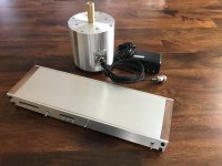
There is a jumper on the board to accommodate both 50 and 60 Hz operation. Details in the manual pdf at beginning of thread....doh to slow. Will cover up with a semi-money shot...hope to be spinning with it by the weekend.
Oh damn, that's nice! Bravo!
Interesting,
I would like to see what you come up with.
I made a remote stby & speed selector switch for mine that is near the turntable. I tend not to make speed adjustments once they're set so this works fine. I'm making a smaller version with micro buttons and will machine buttons to work with them.
Cheers,
Gregory
Hi,
Very, very nice! I like the idea of a separate standby switch so I mounted one next to the rotary encoder. Love it! Just 2 short wires soldered to the Ground & Standby points at the encoder board. Your idea encouraged a practical solution to have a remote like yours needing a 3 wire connection, ground being common for both 33/45 switch and standby switch and plugged to the back panel with a 3.5mm stereo jack & plug. Perhaps I'll also omit having a speed selector switch at the front panel, just encoder knob, power switch and LED display, that's it. Neat!
PCB Layout question
Is it possible to get a dimensioned drawing of the PCB? This would be helpful in creating the front panel. I assume this information is contained in the Gerber files but I don't know how to derive it from them. My apologies if this information is already available. I've been all the way through this thread and can't seem to find it.
Thank you.
- Home
- Source & Line
- Analogue Source
- DIY 4 Phase Sinewave Generator for Turntable Motor Drive