Hi Bill,
I noticed something weird at the SG4. I don't know if anything gone wrong on the board due to build but I'm almost sure its not.
Once a while there's 2 events that may occur..its intermittent when start from cold.
1) It will show FAC on display and hang there as if it were reinitializing itself again. Disconnect the DC and restart, it may be cured and thereon run as designed.
2) For some reason, it may suddenly do a fast frequency upwards, as if my finger were pressing the up button. I've to stop it by turning down the encoder or switching it off.
I will try to solve this myself and will swap the encoder module and see if that's the source of the problem.
If the shows "FAC" then both the plus and minus buttons are stuck at a low state; it will show that display until both buttons are released.
A fast frequency upwards, means the plus button is stuck at a low state.
Depending on the rotary switch, one or both outputs may be stuck at low or the 4013 on the encoder PCB could be bad.
A fast frequency upwards, means the plus button is stuck at a low state.
Depending on the rotary switch, one or both outputs may be stuck at low or the 4013 on the encoder PCB could be bad.
If the shows "FAC" then both the plus and minus buttons are stuck at a low state; it will show that display until both buttons are released.
A fast frequency upwards, means the plus button is stuck at a low state.
Depending on the rotary switch, one or both outputs may be stuck at low or the 4013 on the encoder PCB could be bad.
Thanks Bill,
I will swap the encoder entirely and monitor the situation.
I have roughly zeroed to the root cause of the problem. I replaced the 4013 chip (since I have spares lying around but that didn't cure the problem) My gut feeling told me to zero in on the encoder itself, it could be anything else. At last, its the rotary encoder itself. I bought 2 different types and fixed them with 2 encoder pcb. One is for another SG-4 build. They do work properly, but this particular encoder (the one that gave trouble) looks cheaper build quality. I thought its about the same anyway and likely not to give any trouble but it did! What happen is I've not assembled everything yet and everything is in the open. I fixed a used amplifier knob which is quite heavy that makes it easier to rotate but it seeems at times it could stress the encoder shaft shaft to one side and emit some unwanted signal to the SG4. I know it sounds funny but this is an isolated case. I will discard this rotary encoder and seek a better and more reliable one instead. I can't be too trusting on those cheap Arduino encoders that seems to look perfect. Hopefully the problem doesn't recur.
Last edited:
Hi fellow DIYers
I have handled the SG4 orders for over a year, and have fulfilled 70 orders. I am kinda burnt out with this, plus I'm super busy remodeling my new to me old house, among other things. I would like to not continue. I am currently out of stock, and have a standing order (unfulfilled) for 3 SG4s. Is there anybody out there who could take over distribution in the US? The orders have really slowed down, so really shouldn't be a big deal.
Regards,
twystd
Ventilation
Hi Bill
Thank you for this very well thought out and supported project. I was able to properly finish balancing the channels of my MA3D with your guidance in the other thread.
My new drive system is pretty much finished except for some details with its case and getting a few things on my table sorted so I can set it up with the new system.
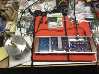
One question I had was about ventilation for the boards in the case I’ve built. As you can see in the picture I’ve attached, I have integrated my Roadrunner into the same case as the SG4 and MA3D. There was no ventilation in the original case of the Roadrunner to speak of. I designed my case to be compact enough to slide in under my turntable and since it is tightly packed with the SG4 and MA3D I am wondering if I need to ventilate the case for one or more of the boards?
Also, is it normal to get a slight “flutter” from the motor as it initializes rotation? I have noticed this when I was testing for rotation direction with some tape on my pulley as I switched between reversing the polarity of the 120 and 240 phases with the dpdt switch I integrated for this purpose.
I appear to have been able to make myself a pulley that is concentric to about .0003-.0005 as read on my dial indicator during testing on the motor. Not sure if any of that is in the bearings on the motor or if it’s all in the pulley. I was struggling a bit turning it on my old Logan lathe. It may not be good enough for rim drive.
Hi Bill
Thank you for this very well thought out and supported project. I was able to properly finish balancing the channels of my MA3D with your guidance in the other thread.
My new drive system is pretty much finished except for some details with its case and getting a few things on my table sorted so I can set it up with the new system.
One question I had was about ventilation for the boards in the case I’ve built. As you can see in the picture I’ve attached, I have integrated my Roadrunner into the same case as the SG4 and MA3D. There was no ventilation in the original case of the Roadrunner to speak of. I designed my case to be compact enough to slide in under my turntable and since it is tightly packed with the SG4 and MA3D I am wondering if I need to ventilate the case for one or more of the boards?
Also, is it normal to get a slight “flutter” from the motor as it initializes rotation? I have noticed this when I was testing for rotation direction with some tape on my pulley as I switched between reversing the polarity of the 120 and 240 phases with the dpdt switch I integrated for this purpose.
I appear to have been able to make myself a pulley that is concentric to about .0003-.0005 as read on my dial indicator during testing on the motor. Not sure if any of that is in the bearings on the motor or if it’s all in the pulley. I was struggling a bit turning it on my old Logan lathe. It may not be good enough for rim drive.
Attachments
If the "flutter" is only at start up, it may be from the voltage ramping up from zero. This is done in the SG4 primarily for the applications where an amp is driving one or more step up transformers; if the output is started at full voltage, the xfmrs present a very low impedance for the first second or so. By ramping the voltage, it prevents the output amps from shutting down due to overload.
Once the motor is up to speed, it should run nearly silent.
The SG4 will generate very little heat (about the same as the Eagle controller); the MA3D should also run fairly cool, so I don't think you will need any additional ventilation.
Great looking case by the way, both the motor pod and the controller.
BTW, you can power the RR tach from the same 15VDC supplying the MA3D and the SG4.
Hi All
I had posted for someone to take over distribution of the SG4s and got no replies. I decided to continue, however I'm going to raise the price to $12 each. That is more in line with what ralphcooke charges for European distribution. The mark up helps with making it more worthwhile for me to do. I hope you all understand.
twystd
If the "flutter" is only at start up, it may be from the voltage ramping up from zero. This is done in the SG4 Pprimarily for the applications where an amp is driving one or more step up transformers; if the output is started at full voltage, the xfmrs present a very low impedance for the first second or so. By ramping the voltage, it prevents the output amps from shutting down due to overload.
Once the motor is up to speed, it should run nearly silent.
It is only at start up as far as I can tell. The motor runs quietly even though I haven’t yet reloaded it with the leadshot after installing the umbilical. I read about the voltage ramp up in some of the original information you posted about the SG4. I thought it was related to preventing burnout of the belts on the platter, but I also remember the issue of the amps shutting down due transformer load. I’m brainstorming about a way to build a separate chassis that would contain step up transformers so I could just connect it to this unit and drive some of the other tables I have that would require the step ups, particularly an old Rek O Kut idler I have.
Great looking case by the way, both the motor pod and the controller.
BTW, you can power the RR tach from the same 15VDC supplying the MA3D and the SG4.
Thanks very much. The fabrication always presents it’s own set of problems. I enjoy building things. I’m running the Roadrunner off the 12V output of the MA3D with the SG4. I had asked about that previously... thanks for that guidance as well. I hid it’s power supply wiring under the boards and soldered it to the the bottom of the RR board. The RR power jack is closed off on the back of the case.
I’m brainstorming about a way to build a separate chassis that would contain step up transformers so I could just connect it to this unit and drive some of the other tables I have that would require the step ups, particularly an old Rek O Kut idler I have.
I wouldn't use these amps to drive step up transformers for a number of reasons:
1. They are only rated to 10W/channel and would likely be unable to drive the low impedance at start up, even with the voltage ramp up. They are also too small to drive the motor.
2. The outputs have 7.5VDC on them, you cannot connect them to a xfmr without coupling caps. On the AA motor, all 3 windings see the same 7.5VDC so there is no offset and no DC current flows.
3. The ROK motor is most likely expecting 60Hz drive signals for 33 RPM. The AA motors are running at 20Hz. You would have to reset the freqs for both 33 and 45 when switching between them.
Hi All
I had posted for someone to take over distribution of the SG4s and got no replies. I decided to continue, however I'm going to raise the price to $12 each. That is more in line with what ralphcooke charges for European distribution. The mark up helps with making it more worthwhile for me to do. I hope you all understand.
twystd
Thanks twystd, for continuing to distribute the chips.
I wouldn't use these amps to drive step up transformers for a number of reasons:
I thought there might be an issue with using them, but I hadn’t thought it through or been in the other threads for awhile.
I knew I was going to want to get the 0 and 90 degree phase signals out of this case anyway if I was going to drive the ROK or my Dual 1019 motors, and I knew I didn’t have a channel to amplify the 90 degree phase.
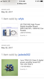
I suppose I could just route the unamplified phase signals I need out through a second umbilical port and house amps and tranny’s for the single phase motors in another case. I’ve horded some amps (pic) that were being suggested at one point for use in driving the single phase motor tranny’s and some suggested for the AA motor before you came up with the MA3D.
I realize I would be dealing with different drive frequency adjustments. I bought multiple boards and components and could build another dedicated SG4, but it would be nice to at least try using what I’ve already built.
Attachments
Please, I´m about to use the SG4 with a Lenco L75, but noticed that it already has a capacitor installed at the power switch under the chassis.

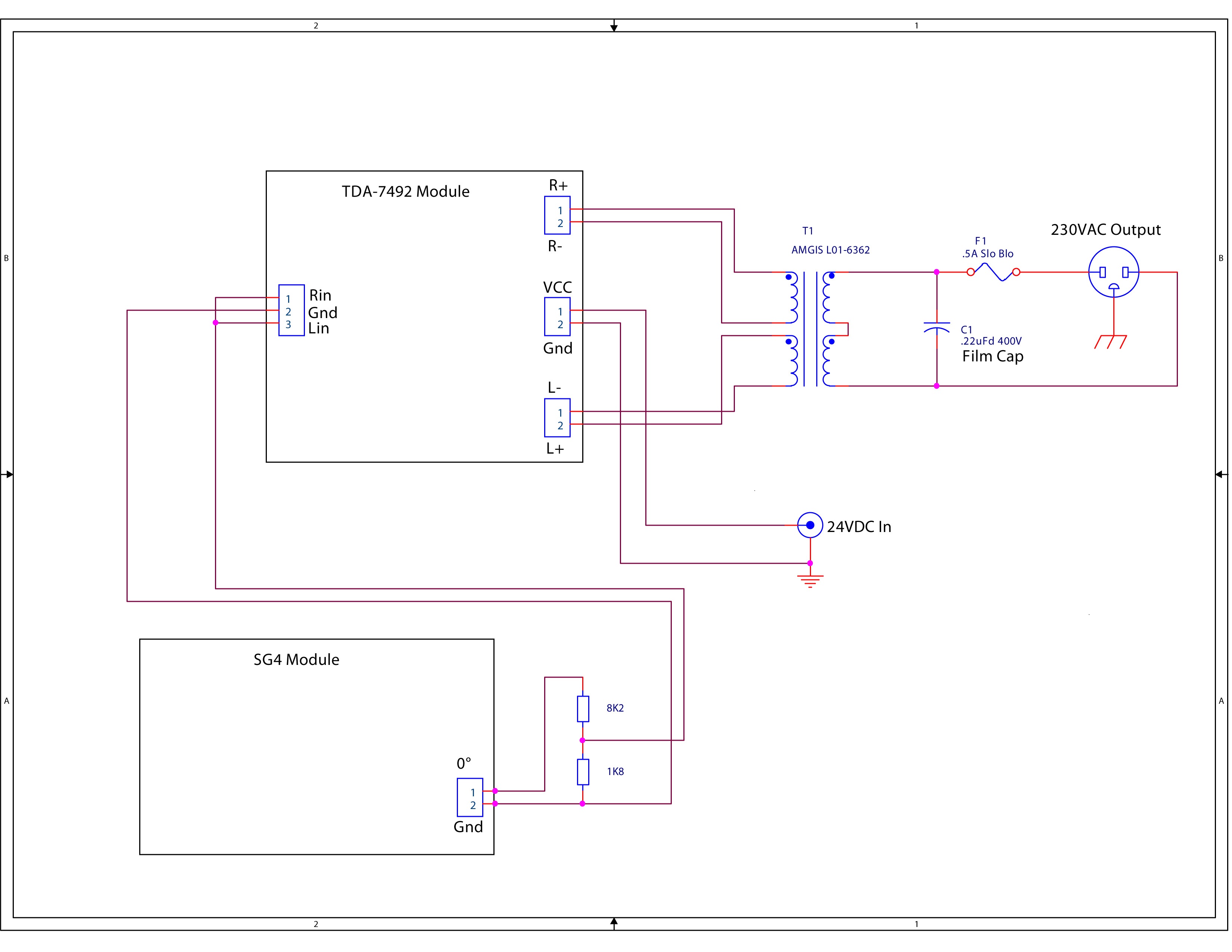
So, do I keep the original configuration for a monophase motor with the .22 uF capacitor at the transformer output or remove one of the capacitors from the circuit?
So, do I keep the original configuration for a monophase motor with the .22 uF capacitor at the transformer output or remove one of the capacitors from the circuit?
Attachments
The capacitor on the Lenco switch is for arc suppression. You should install the .22uFd cap across the transformer output as shown in the schematic. It is needed for filtering as well as high frequency stability.
Leave the Lenco power switch in the on position and start/stop the platter with the SG4 standby function. If you want to retain the removal of the idler from the motor to prevent flat spots, then jumper over the switch so that it is always "on" and engage/disengage the idler when done listening.
Leave the Lenco power switch in the on position and start/stop the platter with the SG4 standby function. If you want to retain the removal of the idler from the motor to prevent flat spots, then jumper over the switch so that it is always "on" and engage/disengage the idler when done listening.
Hi All
I had posted for someone to take over distribution of the SG4s and got no replies. I decided to continue, however I'm going to raise the price to $12 each. That is more in line with what ralphcooke charges for European distribution. The mark up helps with making it more worthwhile for me to do. I hope you all understand.
twystd
Thank you for continuuing the distribution. Much appreciated
Hi!
Is there a difference between the US SG4 processor and the European one? 50hz vs 60hz?
Marc
No difference. The SG4 can be set to any frequency between 1.00Hz and 90.00Hz for both 33 and 45 RPM. Jumper JP1 changes the factory default setting of 50/67.5Hz (jumper in) and 60/81Hz (out).
No difference. The SG4 can be set to any frequency between 1.00Hz and 90.00Hz for both 33 and 45 RPM. Jumper JP1 changes the factory default setting of 50/67.5Hz (jumper in) and 60/81Hz (out).
Thank you for the quick answer!
Marc
- Home
- Source & Line
- Analogue Source
- DIY 4 Phase Sinewave Generator for Turntable Motor Drive