The load of the AS is less then 100pF (for the high frequencies) so it will be 20kHz (but the foil is 6micron so still difficult)
the Es100 wont get to 20khz ?? with load.
i failed to get the tranies this weekend same goes for the impedance measurements. had a huge hangover on saturdayand now its sunday and the shop is closed.... its a shame. hope ill manage to get them this week
btw any change you might share the design ? i got a winding machine so.
ok so i made this measurement jig from REW5
http://www.roomeqwizard.com/REWV5_help.pdf
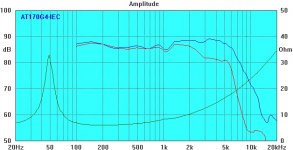
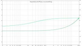
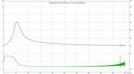
then i foolowed the REW help file and measured my first loudspeaker the AUDAX AT170G4, one that i had laying around just to confirm its working,
seen in picture one is the measurement of AUDAX and picture 2 is mine, as you can see, they are almost the same not much difference.
then i thought now i can finally measure my ESL's.
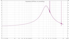
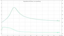
3rd picture is tranfornmer without panels connected
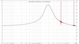
4th trannie with panels and capacitor of 47 uF and a 0.8 Ohm resistor in series.
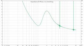
5th tranny with panels cponnected without anything else.
it does not look good, i recon the headphone amplifier does not like to drive such low impedances i guess ?? it sounds distrorted as i run the measurement, and the graphs does not look to good either. the Normal driver i tested did look good so might it be the impedance to low? shal i try it with a power amp tomorow ? on low volume ofcourse dont want to blow up my soundcard.
any ideas or able to confirm my suspicion
BTW ignore the 2 peaks , this is apparantly my line in or the phones out wich suck, its also in the calibration
http://www.roomeqwizard.com/REWV5_help.pdf
then i foolowed the REW help file and measured my first loudspeaker the AUDAX AT170G4, one that i had laying around just to confirm its working,
seen in picture one is the measurement of AUDAX and picture 2 is mine, as you can see, they are almost the same not much difference.
then i thought now i can finally measure my ESL's.
3rd picture is tranfornmer without panels connected
4th trannie with panels and capacitor of 47 uF and a 0.8 Ohm resistor in series.
5th tranny with panels cponnected without anything else.
it does not look good, i recon the headphone amplifier does not like to drive such low impedances i guess ?? it sounds distrorted as i run the measurement, and the graphs does not look to good either. the Normal driver i tested did look good so might it be the impedance to low? shal i try it with a power amp tomorow ? on low volume ofcourse dont want to blow up my soundcard.
any ideas or able to confirm my suspicion
BTW ignore the 2 peaks , this is apparantly my line in or the phones out wich suck, its also in the calibration
Attachments

Does anyone know how to calculate an LCR resonant paralel tofilter increase the impedance without losing high frequencys?
like discribed int this link
http://mnierop.home.xs4all.nl/esl_boek_fikier/Hoofdstuk04x.pdf
sorry its dutch search for LCR kring.
i wanted to try this to see ig it makes any diference in distortion, but cant seem to find how to calculate the L C and R
like discribed int this link
http://mnierop.home.xs4all.nl/esl_boek_fikier/Hoofdstuk04x.pdf
sorry its dutch search for LCR kring.
i wanted to try this to see ig it makes any diference in distortion, but cant seem to find how to calculate the L C and R
well changed output channel from the Digi 003 wich is incredible expensive compared to the onboard Hd audio line out..... but the artifacts
come from the 003. wich is probable 1000 times more expensive then the onboard card. but hell why not
i now changed the line out to the line out from the onboard soundcard.
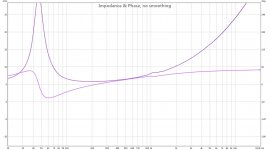
Picture 1 the AT170G4 impedance plot
picture 2 for testing purpose a coil of 0.1 mH program says its 101 uH wich is 0.101 mH so pretty damn close
pisture 3 a cap of 22uF program says 21.9 uF
look pretty accurate, and im verry pleased. now fix the trannie problem ill redo the measurements and hopefully someone can shed a light on the isue.
come from the 003. wich is probable 1000 times more expensive then the onboard card. but hell why not
i now changed the line out to the line out from the onboard soundcard.
Picture 1 the AT170G4 impedance plot
picture 2 for testing purpose a coil of 0.1 mH program says its 101 uH wich is 0.101 mH so pretty damn close
pisture 3 a cap of 22uF program says 21.9 uF
look pretty accurate, and im verry pleased. now fix the trannie problem ill redo the measurements and hopefully someone can shed a light on the isue.
Attachments
it does not look good, i recon the headphone amplifier does not like to drive such low impedances i guess ?? it sounds distrorted as i run the measurement...
If you were using the REW impedance measurement setup, you have a 100ohm resistor in series with the load, so the headphone amplifier should have no problem driving it. The sound is distorted for the same reason it was when driven with an amplifier and you put a capacitor in series with the primary.
Looking at the extremely low impedance for frequencies < 500Hz, you can calculate that the primary inductance of the transformer is only about 0.65mH. This is way to low for use as a full range transformer or with a passive crossover. For a full range you would want primary inductance to be at least 100x higher, perhaps 20x higher for a passive crossover around 300Hz.
The low primary inductance is the reason for the distortion when you put a capacitor or large resistance in series with it. With this primary impedance below 1Khz, any distortion in the current driving the transformer(due to core properties) results in a substantial distorted voltage drop across the series capacitor or resistor. If the primary impedance was higher, a much small distorted voltage drop would occur.
You mentioned that the transformers came from an ESL that used an active crossover. Use of the active crossover allowed the manufacturer to use a low primary inductance(fewer primary turns) which makes it easier to get an extended HF response without complicated winding geometry.
Thanks bolsert !
first the company did use these transformers with a passive crossover as well, so i really have no clue how, because if you are right then they all would sound like this on low volume. wich sucks big time !
i noticed that the distortion i heard during the measurement was in fact the line out being distorted (set to high)
Well REW says indeed that the inductance is 550 uH until 1 Khz.... wich is close to the 0.65mH you mentioned.
is there a way to compensate for it ? how about using 2 in series >? or by using the LCR resonace circuit to increase impedance ?
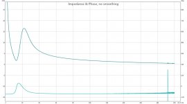
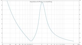
i got one other tranformer here, the Audio 4 tranformer, seen in attached picture this one looks beter in peformance. if i can rememember correct i had the same distortion with it. at least the impedance plot looks better. it does not drop below 1.6 ohm still low
this plot is with a cap of 22uF on it without any resistor.
this trannie was never intended for fullrange, what do you think ?
Attachments
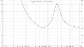
because this tranformer is made out of 2 bobines on 2 C cores i could also put the primairies in series instead of paralel wich gives me this picture. i did not test yet what the bandwith would be in this config. and if i lose allot of high frequencys. and im not sure yet what other bad things come form it? saturation ? wel lets see what happens in rela life , gone move these heavt speakers again to take a listen
Attachments
Last edited:
As far as i know this T300 is a single loop c-core transformer with transformation 1:x ( i don't know which step up your version has, i guess 1:150)
The two primary windings should be parallel and the secondaries in serie.
There must be something serious wrong (in the transformer or your measurements)
The two primary windings should be parallel and the secondaries in serie.
There must be something serious wrong (in the transformer or your measurements)
because this tranformer is made out of 2 bobines on 2 C cores i could also put the primairies in series instead of paralel wich gives me this picture. i did not test yet what the bandwith would be in this config. and if i lose allot of high frequencys. and im not sure yet what other bad things come form it? saturation ? wel lets see what happens in rela life , gone move these heavt speakers again to take a listen
Last edited:
As far as i know this T300 is a single loop c-core transformer with transformation 1:x ( i don't know which step up your version has, i guess 1:150)
The two primary windings should be parallel and the secondaries in serie.
There must be something serious wrong (in the transformer or your measurements)
Whoops mean 2 bobines on a single loop C core. transformer factor of this example is the older 1:120. the first measurement here atached is of the stock T300 primary in parallel second in series impedance plot. whats wrong with it ?
do notice there is a cap in place of 22uF
but according to bolsert the primary inductance of the T300 is also to low, if i understand it correct. hence the idea of putting the primary in series. this results in a to high inductance, and i lose some high frequency. since i wind these bobines for the audio4 transformers , i could make 2 new ones with not 3 wires for the primary parralel but 2 and increase the windings from 27 to 40, then put the 2 bobines in parallel. like it was designed.? so i end up with not 2 times the primary windings (when i put them in series) but 1/3 extra.
Attachments

Last edited:
Chancing the turn ratio can have a effect on the secondary phases. (you want equal frequency response for each phase) Specially if you change the primary windings.
With a capacitor in serie you create an LC resonance circuit.
With a capacitor in serie you create an LC resonance circuit.
Whoops mean 2 bobines on a single loop C core. transformer factor of this example is the older 1:120. the first measurement here atached is of the stock T300 primary in parallel second in series impedance plot. whats wrong with it ?
do notice there is a cap in place of 22uF
but according to bolsert the primary inductance of the T300 is also to low, if i understand it correct. hence the idea of putting the primary in series. this results in a to high inductance, and i lose some high frequency. since i wind these bobines for the audio4 transformers , i could make 2 new ones with not 3 wires for the primary parralel but 2 and increase the windings from 27 to 40, then put the 2 bobines in parallel. like it was designed.? so i end up with not 2 times the primary windings (when i put them in series) but 1/3 extra.
Last edited:
ok i might found the solution for the cheap tranies. i always used an first order filter. i now for fun tried a second order since i know the impedance curve. swaping only a cap was not so hard but a cap and a coil for a second order filter you cant use the trial and error method.
i calculated the needed cap and coil in winisd, rewinded a larger air coil i had around and measured it with the impdance jig. first to proof its on point i measured the original value and it was spot on, so now i just rewinded half of it then measured again , then fewer turns rewinded until i got the needed inductance.
This is what happens, i tried serval caps 22uF 15uF 10 uF 7uF and a 47 nF i know this is way to low but wanted to see what happened.
well with all caps the crossover frequency did not change much , it creeps slowly higher, more obious was the level going down with every smaller cap. just when i used the 47nF the crossver whas at 1300Hz ?????? and the level droped to -20dB or so. then i thought well let try a second order. calculated for 1000+- hooked it up , no level drop at all, and i tried serveral recording with piano and bells at verry low listening levels to get the distortion that is haunting me for almost 7 years l!!.
I only cant explain why this seems to work, any one a idea >?? only thing i can come up with is increased inductance from the coil in the filter itself wich helps ? the induction problem bolsert stated ?
With a capacitor in serie you create an LC resonance circuit.
yeah if i used the formule corectly from wikipedia, and use the inductance value bolsert calculated i come on a resonance fequency of 1300 Hz with a 22uF cap in series with the trannie.
still not sure what the direct result would be.
damn im so hyped the thing playes like i want finally. hope i wont be dissapointed tomorow. sometimes hard to be critical after so many hours fidling, listening fatigue, and prob effort
you probably have a problem with core saturation (also because the LC resonance)
I don't know which transformer, is see more then 1, you use but the A4 transformer has a big problem with core saturation below 1000Hz (and winding capacity too).
If the transformer you use has not an (good designed) airgap the induction is not constant enough. That means your filter is not work good, it has a drift....
Last edited:
hmmm well i used the solosounds because i still have 2. the A4 is a loan i only wind the bobines here, i dont have the C cores and neither do i have a the faintest idea of designing a trannie. except the paper on the diy ESL club in holland, and by the looks of it, he is the one designed the tranies from A4. they are prety much 1:1. im prety happy with the solosound now when using a second order filter and crossing them at 1K, before that all attemps to cross them high with a first order filter failed. this could be because of the saturation you mentioned. i would love to wind my own simple tranies for use of 300 Hz and up, since ive seen people using cheap teroids for exact this purpose how hard can it be to sesign one with a C core?
The 550uH sounds reasonable. My estimate of 650uH assumed all of the impedance was coming from the inductance. (ie any resistance in the wires or connections was not considered)Well REW says indeed that the inductance is 550 uH until 1 Khz.... wich is close to the 0.65mH you mentioned.
is there a way to compensate for it ? how about using 2 in series >? or by using the LCR resonace circuit to increase impedance ?
There is no easy way to increase the impedance without affecting the response.
It is hard to tell what the primary inductance of the Audio 4 transformer is from this plot.i got one other tranformer here, the Audio 4 tranformer, seen in attached picture...at least the impedance plot looks better....this plot is with a cap of 22uF on it without any resistor.
Can you re-measure without the 22uF?
ok i might found the solution for the cheap tranies. i always used an first order filter. i now for fun tried a second order...calculated for 1000+- hooked it up , no level drop at all, and i tried serveral recording with piano and bells at verry low listening levels to get the distortion that is haunting me for almost 7 years l!!.
I only cant explain why this seems to work, any one a idea >??
Distortion will be less since the inductor is in parallel with the primary so current thru it will tend to swamp the effect of the distorted current thru the primary. Also, the HP cuttoff is sharper as you noted so distortion from higher current draw at lower frequencies where the primary impedance drops so low is minimized.
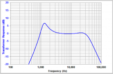
What inductance and capacitance values did you use for your second order filter?
Did you include any resistance in series or parallel with the inductor?
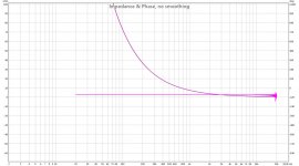
If you did not include any resistance, the filter response will be underdamped and you probably have a large peak in the response before roll-off...something like the attached pic.
You might measure the response from the secondary of the transformer to see.
Also, if you measure the impedance, you will also probably find a dip in the impedance at this same frequency.
This underdamped response is not neccessarily all bad.
If properly defined and controlled with some resistive damping, the response peak from a second order HP filter can be used to compensate for some of the inherent LF roll off of a dipole ESL. It does, however, make the load impedance more difficult for the driving amplifier.
Attachments
The 550uH sounds reasonable. My estimate of 650uH assumed all of the impedance was coming from the inductance. (ie any resistance in the wires or connections was not considered)
There is no easy way to increase the impedance without affecting the response.
It is hard to tell what the primary inductance of the Audio 4 transformer is from this plot.
Can you re-measure without the 22uF?
Distortion will be less since the inductor is in parallel with the primary so current thru it will tend to swamp the effect of the distorted current thru the primary. Also, the HP cuttoff is sharper as you noted so distortion from higher current draw at lower frequencies where the primary impedance drops so low is minimized.
What inductance and capacitance values did you use for your second order filter?
Did you include any resistance in series or parallel with the inductor?
If you did not include any resistance, the filter response will be underdamped and you probably have a large peak in the response before roll-off...something like the attached pic.
You might measure the response from the secondary of the transformer to see.
Also, if you measure the impedance, you will also probably find a dip in the impedance at this same frequency.
This underdamped response is not neccessarily all bad.
If properly defined and controlled with some resistive damping, the response peak from a second order HP filter can be used to compensate for some of the inherent LF roll off of a dipole ESL. It does, however, make the load impedance more difficult for the driving amplifier.
ur a genius
i indeed did notice the Hump (not as big as in your picture) i used a 0.26mH paralel to the transformer and 69uF in total of caps in serie.when i calculated the the caps i needed a lower value but i noticed this hump at the crossover frequency, i then just increased and decreased the capacity a bit and moved the resistor from the trany to between the caps and the inducter coil so in between the cap and de coil. and exactly as you say its damps that peak
funny you just verify what i found out playing around with it . nice to know its the way to go. i used a resistor of 1 ohm 5 watt., wanted to use more but that would cost me some high frequency extension. so there is a tiny hump left.i will do a new measurement of the trannie from A4 without the cap and some better screenshot (with a panel connected or without?). could you give me some pointers to make a better trannie ? i got a winder, bobines, 0.8mm wire for primary and 0.3 for sec, and nomex insulation. its all on loan but i could try a new trannie and buy my own suplly's needed to make my own trannies, for my own stats. (adn repay the stuff i used for testing ofc)
Last edited:
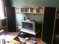
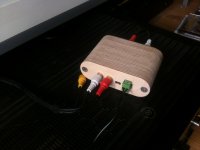
some pics of the almost finished speakers. dont mind the bad image quality and the dust seen of some of the cloth. this is normally not seen, and i must admit i still have to clean eveything propper the boxes on the back have half of the height filled with sand (thats why they are so high) so it keeps the whole thing up. Bass is done by a bass panel of an Magnepan MG 1C, mid high 7 panels of 10cmx15 cm.
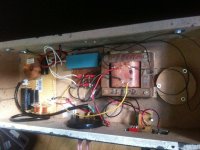
HV consist of a inverter driven by a Lm317 so i can cotroll the high voltage. the switch at the back is used to short the HV and drain the caps after decreasing the high voltage by the pot. since the caps and the panels hold charge you had to wait 30 minutes before you know what the result of the change in HV has on the sound. (or i had to short them with a piece of wire everytime...... got sick of it)
last picture is of my home made wooden casing of the minidsp. i did end up buying one , i might maybe when i find a nice second amplifier do it full active but for now i only use it for some rework of my room. wich is incredible hard to measure with these dipoles.
the boxes on the back have half of the height filled with sand (thats why they are so high) so it keeps the whole thing up. Bass is done by a bass panel of an Magnepan MG 1C, mid high 7 panels of 10cmx15 cm.HV consist of a inverter driven by a Lm317 so i can cotroll the high voltage. the switch at the back is used to short the HV and drain the caps after decreasing the high voltage by the pot. since the caps and the panels hold charge you had to wait 30 minutes before you know what the result of the change in HV has on the sound. (or i had to short them with a piece of wire everytime...... got sick of it)
last picture is of my home made wooden casing of the minidsp. i did end up buying one , i might maybe when i find a nice second amplifier do it full active but for now i only use it for some rework of my room. wich is incredible hard to measure with these dipoles.
Attachments
Last edited:
Had you measured the impedance with this setup? I would think impedance will drop to a very low value(not much above the series resistance) around 1kHz.i indeed did notice the Hump
Looking at your previous impedance measurements again, I noticed that the magnitude of your impedance peak is not nearly as high as I am used to seeing. Normally I will see Zmax of 100 to 500 ohm. Yours was < 20ohm. With no load connected, the impedance peak is due to parallel resonance between primary inductance and winding capacitance. The magnitude of the impedance peak is an indicator of core(and other) losses. All other things being equal, a better core will result in larger impedance peak value. If there were no losses, the magnitude would trend toward infinite. Your low value of Zmax may be why esltransformer suggested there may be something wrong with the transformer.
The low value of Zmax mentioned above indicates there are higher than average losses in the transformer that are also damping your 2nd order crossover producing the smaller response hump.(most likely also part of why you were getting distortion with only a series capacitor)
One measurement without would tell us the primary inductance.i will do a new measurement of the trannie from A4 without the cap and some better screenshot (with a panel connected or without?). could you give me some pointers to make a better trannie ? i got a winder, bobines, 0.8mm wire for primary and 0.3 for sec, and nomex insulation.
If you take another measurement with the panel connected and know what the panel capacitance is, we could also estimate the leakage inductance.
I could provide some suggestions for winding your own transformer with the wire you mentioned.
I would need to know:
1) core type and dimensions
2) bobbin dimensions, and number of bobbins
3) ESL capacitance to be driven
4) Desired crossover frequency
After 35 yrs with ESLs, this is the first time I did a freq response with the old Thordarson 10k-primary tube output transformers that drive my tweeters for last 30 yrs, all connected in-situ (except bias was off!).
Tweeter system, with the input charted in the range about 1kHz to 20kHz, roughly usual power level. Barring measurement goofs on my part, the output looked identical to input. No bumps, nothing odd. Sorry I have no REW charts just now, but you can take my word for it.
Ben
Tweeter system, with the input charted in the range about 1kHz to 20kHz, roughly usual power level. Barring measurement goofs on my part, the output looked identical to input. No bumps, nothing odd. Sorry I have no REW charts just now, but you can take my word for it.
Ben
- Status
- This old topic is closed. If you want to reopen this topic, contact a moderator using the "Report Post" button.
- Home
- Loudspeakers
- Planars & Exotics
- distortion From ESL at low level