i tried polarized 1000uF 100 volt, no result  exactly the same..got 3 of 1000 willtrie triple it to see if it amkes any difference
I also tried active crosover on laptop and when i chose the same crossover there is no distortion or strained sound at all something still weird, and it has at least something to do with the cap or trannie/amp
exactly the same..got 3 of 1000 willtrie triple it to see if it amkes any differenceI also tried active crosover on laptop and when i chose the same crossover there is no distortion or strained sound at all
something still weird, and it has at least something to do with the cap or trannie/ampWhat happens if you lower the Bias voltage?
You never stated what it was, or did I miss that part?
If you do a sweep test does the distortion only occur at the highest and lowest frequency's of the sweep?
There lots of factors of your setup that you have explained to us yet.
Such a distortion could even be caused by leakage in the panel it self such or a bad connection or a resistor if any are used.
Check for any high resistance shorts in the construction as it seems that something is loading the amp down.
I once had this problem in one of my wire mesh designs and it turned out to be some kind of bad connection in the mesh as it totally relied on the connections at the crosshairs of the cross wires to energize the whole stator.
This was because the material is made of aluminium and it has an oxide layer on it that will cause thing not to conduct.
Since then I etch the mesh in lye before I coat them to get rid of the oxide layer.
It eventually went away and stopped making the noise as it only happened at a low volume when the voltages are not very high.
In fact sometimes the panel would not work at all and pop in once I raised the volume a bit.
A few other times I had an issues where the Licron (the original formula called Licron and not the Crystal formula) would crack around the perimeter of the frame causing either an intermittent charging or no charge on the diaphragm at all!!!
Leaving for a dead ESL all together!
I also I mention the bias voltage because when I First started, I was using some old 6V6 OPT's and I was running a very high bias voltages later on and they eventually gave out making distortions and arcing on the inside and such.
By lowering the bias voltage they would clear up.
But they eventually gave out completely, First one end then the other.
That was why there is a 6 year span of me not continuing on with my designs!!
All because of the stupid transformers!!!
I didn't quite understand what you where trying to explain about your crossover setup but if it is frequency related, then it could be just that it is too low of impedance for the amp at the extreme ends of the bandwidth.
Even if you add a capacitor to protect the dc offset issue, Have you tried just adding any resistance to the primary side?
The DC resistance of the winding itself maybe to low causing the amp to do weird things.
I had this happen to me once with my Crown, But it actually turned out to be an issue of some sort of a ground loop with my scope as I was trying to measure the output of the amp.
It was something that never occurred before with that amp and it would start to motorboat until I put at least a 1 ohm resistor in series with the primary.
Finally that resistor would get hot and it burned up and that is how I found out it was a ground loop issue with the scope as it didn't do it when the scope was not connected.
My cheapy Awia amp did need at least a .47 ohm resistor to stay stable or it would go into oscillation and shut down.
The DC resistance of my self wound primary of about .6 ohm or so was enough to keep it stable.
Maybe the amp is oscillating?
Have you checked this with a scope?
Maybe some of these things you can look for to rectify the situation.
jer
sorry to bring back a very old post, but since i got again the same problems with different panels but same amplifier,same High voltage cascade and same tranies. Also tested with a new transformer (T300), from audio 4 , a person that makes tranformers as upgrade. (same result so trannies should be ok)
You might try returning to the test setup with the T300 transformer where you used headphones to listen to the low level signal upstream and downstream of the capacitor.
Setup description(post#20): http://www.diyaudio.com/forums/planars-exotics/226637-distortion-esl-low-level-2.html#post3310161
Your previous results were distortion after capacitor but not before(post#23):http://www.diyaudio.com/forums/planars-exotics/226637-distortion-esl-low-level-3.html#post3310695
But, I don't think you ever when the last step and removed the connections to the HV supply and panel.
Try the test with just an amplifier, capacitor, and transformer. Nothing at all connected to the secondary or secondary center tap.
Do you still get distorted sounds when listening with headphones to the low level signal after the capacitor?
If not, start adding things to the secondary until you find the culprit.
If distortion is still there...something odd is going on...more thought required.
What happens if you lower the Bias voltage?
You never stated what it was, or did I miss that part?
If you do a sweep test does the distortion only occur at the highest and lowest frequency's of the sweep?
There lots of factors of your setup that you have explained to us yet.
Such a distortion could even be caused by leakage in the panel it self such or a bad connection or a resistor if any are used.
Check for any high resistance shorts in the construction as it seems that something is loading the amp down.
I once had this problem in one of my wire mesh designs and it turned out to be some kind of bad connection in the mesh as it totally relied on the connections at the crosshairs of the cross wires to energize the whole stator.
This was because the material is made of aluminium and it has an oxide layer on it that will cause thing not to conduct.
Since then I etch the mesh in lye before I coat them to get rid of the oxide layer.
It eventually went away and stopped making the noise as it only happened at a low volume when the voltages are not very high.
In fact sometimes the panel would not work at all and pop in once I raised the volume a bit.
A few other times I had an issues where the Licron (the original formula called Licron and not the Crystal formula) would crack around the perimeter of the frame causing either an intermittent charging or no charge on the diaphragm at all!!!
Leaving for a dead ESL all together!
I also I mention the bias voltage because when I First started, I was using some old 6V6 OPT's and I was running a very high bias voltages later on and they eventually gave out making distortions and arcing on the inside and such.
By lowering the bias voltage they would clear up.
But they eventually gave out completely, First one end then the other.
That was why there is a 6 year span of me not continuing on with my designs!!
All because of the stupid transformers!!!
I didn't quite understand what you where trying to explain about your crossover setup but if it is frequency related, then it could be just that it is too low of impedance for the amp at the extreme ends of the bandwidth.
Even if you add a capacitor to protect the dc offset issue, Have you tried just adding any resistance to the primary side?
The DC resistance of the winding itself maybe to low causing the amp to do weird things.
I had this happen to me once with my Crown, But it actually turned out to be an issue of some sort of a ground loop with my scope as I was trying to measure the output of the amp.
It was something that never occurred before with that amp and it would start to motorboat until I put at least a 1 ohm resistor in series with the primary.
Finally that resistor would get hot and it burned up and that is how I found out it was a ground loop issue with the scope as it didn't do it when the scope was not connected.
My cheapy Awia amp did need at least a .47 ohm resistor to stay stable or it would go into oscillation and shut down.
The DC resistance of my self wound primary of about .6 ohm or so was enough to keep it stable.
Maybe the amp is oscillating?
Have you checked this with a scope?
Maybe some of these things you can look for to rectify the situation.
jer
ill try to anwser as many as i can
i used bias of 6Kv and used every step in betweet the cascade , but decreasing the bias has no effect on the distortion. also if i remove the bias lead to the panel (then its still charged) it still distort
the distortion is more audible then measureable with sweeps, because it only happens with low volume, to low for measurements. but enough for me sitting on a couch going nuts about this weird sound, as if its held back or stuck to one stator, wich it is not. so the audible distortion looks to be most pronounced in the mid/low's piano with all harmonics tend to sound the worse, especially the decay. in sweeps i wont notice a big difference.
Resistance shorts, or bad resistor. i used several panels with and without resistors. just plain PCB panel with PCB Pvc spacer menbrane pvc spacer PCB distorts. and its only a panel of 10x15cm with licron as coating. not allot of things can go wrong with such small panel i guess.
the others panels are from wire, thats runs up and down looped so only 3 connections are made 2 for the segmentation and one that goes to the tranformer.
Resistance to primary. yes tried it as well from 1 ohm to 2.2 up to 15 ohm no change.
about the bias, i have 2 biases from solosound rated at 5.7kv acording to specs (got no meter that can handle such voltage)
both are simple cascades without even 2 transformers one forwared one backwards. only 2 resistors one to the 0 on the tranie and one to the bias lead . its a small resitor so the current cant be that high. the rest are diodes and caps. both resitors are working fine. also my gues when i remove the bias lead. so the panels is holding its own charg should the distortion go away if it had anything to do with the bias ?
hope this anwsers some of the questions everyone might still have.
You might try returning to the test setup with the T300 transformer where you used headphones to listen to the low level signal upstream and downstream of the capacitor.
Setup description(post#20): http://www.diyaudio.com/forums/planars-exotics/226637-distortion-esl-low-level-2.html#post3310161
Your previous results were distortion after capacitor but not before(post#23):http://www.diyaudio.com/forums/planars-exotics/226637-distortion-esl-low-level-3.html#post3310695
But, I don't think you ever when the last step and removed the connections to the HV supply and panel.
Try the test with just an amplifier, capacitor, and transformer. Nothing at all connected to the secondary or secondary center tap.
Do you still get distorted sounds when listening with headphones to the low level signal after the capacitor?
If not, start adding things to the secondary until you find the culprit.
If distortion is still there...something odd is going on...more thought required.
you are right ! i get right on it!!! i get soooooo demoted by this crap
Hope this bare some results
report back to you!You might try returning to the test setup with the T300 transformer where you used headphones to listen to the low level signal upstream and downstream of the capacitor.
Setup description(post#20): http://www.diyaudio.com/forums/planars-exotics/226637-distortion-esl-low-level-2.html#post3310161
Your previous results were distortion after capacitor but not before(post#23):http://www.diyaudio.com/forums/planars-exotics/226637-distortion-esl-low-level-3.html#post3310695
But, I don't think you ever when the last step and removed the connections to the HV supply and panel.
Try the test with just an amplifier, capacitor, and transformer. Nothing at all connected to the secondary or secondary center tap.
Do you still get distorted sounds when listening with headphones to the low level signal after the capacitor?
If not, start adding things to the secondary until you find the culprit.
If distortion is still there...something odd is going on...more thought required.
ok i tried.
results are: connected cap and transformer both the solosound and the T300 wich really should be a decent trannie C core verry long flat bobine.
well if i listen to V1 before the cap with my headphone its sound ok but with some noise could this be impedance mismatch ? or what, sounds like having a soft recording and then put volume half way. i must say the volume knob is just a little bit open because i want to spare my ears and my headphone. could the background his be the noise from the power amp ? after the volume knob ? well any how it sounds not distorted.
then when i ad the cap and the trannie, and listen to V2 after the cap it wil get distorted, if i then listen to V1 it has no distortion or is completly masked.
Then when i listen to V2 after the cap, remove the trannie its sounds not distorted or commpletly masked. i must add by removing the tranformer the impedance from the headphone is so high the crossover frequency drops a huge amount so could mask the distortion a bit in the harmonics.
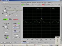
as posted earlier in the thread you mentioned, is also an image of what happens, in the waveform. and it looks i still have this problem with not even having a pannel or the bias connected, just the trannie and a cap.
in the waveform it would looked like the it had a hard time geting positive so the peaks in the negative direction where stronger then the ones in the positive direction(or other way around same idea.)
because i used 2 transformers now i cant believe its the quality that sucks. i mean these are trannies from an comercial ESL that is pretty succesfull an is still around form the 70 until now. and the T300 i heard never complaints about. my basic electronic expertice as far as i have that does not reach far enough to understand whats hapening
Btw before some one askes, i used cheap 10uF cap , 15uF Audin cap, and a MKT 100Volt 15uF cap. i looks like the lower the cap is the more prenounced the effect is
makes me want to stop doing anything at all then, half a year later i try again
with diferent panels dif tranformer.. same story
Last edited:
Maybe for some reason units you have are damaged or defective.
I would advise to try with any transformers laying around. Lamination thickness is important to reduce core losses(eddy currents) so it's best to look for one having <=0,3mm, which is pretty much standard. EI power trafo may work too but with reduced HF limit. Best to try any small toroid core if you have.
Sometimes pretty weird things can happen... Maybe for some reason stability of amplifiers is affected? Although I don't think that's highly probable. You could also try to put resistor of let's say a few ohms instead of cap and do a similar test, or even try to feed from a different source(without a switching power supply : ) )
Regards,
Lukas.
Last edited:
Maybe for some reason units you have are damaged or defective.
I would advise to try with any transformers laying around. Lamination thickness is important to reduce core losses(eddy currents) so it's best to look for one having <=0,3mm, which is pretty much standard. EI power trafo may work too but with reduced HF limit. Best to try any small toroid core if you have.
Sometimes pretty weird things can happen... Maybe for some reason stability of amplifiers is affected? Although I don't think that's highly probable. You could also try to put resistor of let's say a few ohms instead of cap and do a similar test, or even try to feed from a different source(without a switching power supply : ) )
Regards,
Lukas.
i tried the resistor , no change.
well faulty product i tried 3 stepup transformers, 2 small power transformers, and 2 100 volt (in serie) line tranfomer wich worked in the past as well for tweeter dutty.
i am beginning to doubt my amplifer.. although i tested 2 or 3 in the past. tobad i dont have any aplifiers laying around any more.. might buy a cheap one just to see again if the problems persists.
its getting weird
5 panels checked, total of, 6 tranies checked ,3 caps checked. what is left is my amplifer. wich reminds me of a exact same incident 8 years back or so with another ampifier same brand trannies diferent panels, diferent location/house i had this problem to, but i sold the whole thing. never had a solution. this may let me think it was the trannie. but since i now tested 4 tranies more. it gets weird.btw i thought core size was more of a big deal in low frequency response, also why is it a problem with a cap an no problem without? and then why only at low levels listening and not at high ?
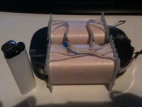
this is the T300 trannie on the picture the lamination is like 0.2 0.3 verry thin anyways. the C core is around 25mm thick
oh btw feed from diferent source you mean other wall socket? or other amplifier? or amplifier on diferent wall socket ?
Attachments
Last edited:
measured my DC offset on the channels, 30mv and 20mv, not really extreme i guess.
Now imagine if you connect this to a toroid directly which has 0.3 ohm resistance as an example. DC current of 100mA is significant for a toroid. Trafo will saturate with much lower AC input voltage at low frequency meaning max. output is reduced.
However the fact that series capacitor didn't solve distortion problem means issue is somewhere else.
Regards,
Lukas.
wil try to get my hands on some trannies from a ES100, 4 years back i had a ES300 and had no problems with this amplifier. although they ofcourse played fullrange........ damn
The ES100s I have worked on all had a 33uF capacitor in series with the transformer primary.
These would be a known good transformer to test and help track down your distortion problem
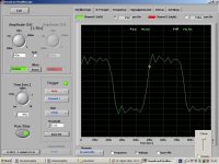
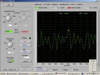
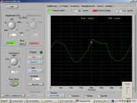
Hi again same problem still, but got this scope program now, im no expert with scopes never used one but i tried making some measurements, if someone has pointers! pls let me know and i will try to perform it, im sick of this werird stuff :9 i want to finally use the stuff i made.
did some tests with this scope program, i measured the output of the tranformer. with 15uF cap and without. on 2Khz and 5khz to be sure to be out of the crossover region
.
1. 2k square wave without cap
2. 2k square with cap
3. 5K without cap
4. 5K with cap.
must say this is the high voltage side measured so i had to keep all output levels low tp not destroy my laptop line in :0 , biut still the diferende is noticable. also tried it with a mic Square waves and saw tooth dit not look anything like the input.. with pure sinewaves they looked PERFECTLY clean. could not fins anything weird. this kind of explains for me while Holmimpulse measuremenst never looked weird.
i also measures before the tranies, frogot to take picture.
i measured before cap with trannie and after the cap with tranie and also after the cap without tranie. only before cap or after cap without trannie connected resulted in Square waves that at least looked like the original
Attachments
Last edited:
You should make the interface I have described in order to to not risk blowing up the inputs of your soundcard.
Full info can be found here,
A TEST JIG FOR FINDING ESL STEP-UP TRANSFORMER PARAMETERS
I have used this for up to 5Kv and it is good for 10Kv safely.
It is very simple to build and is very accurate as long as you take the time to measure and calculate all of the resistors to insure complete accuracy.
I have included trimmer pots in the design for fine adjustments as well.
I use this with Visual Analyzer and other measuring programs as well.
In fact I just finished a new updated version with precision opamp's (LT1057) and I just spent all day and last night testing it out, that's how new it is.
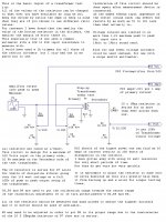
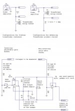
Below is the schematic of the original version and the updated buffer section in the thread as I have shown examples of it in action measuring a transformer at full tilt of 4.5KV of output voltage.
I used the non-inverting opamp configuration in my version.
But I do show both configurations to choose from and have tested both for functionality.
I know this works as when I tested it I was going straight in to my brand new motherboard and didn't have to send it back, under warranty of course(He,he,he,he) ,and ,it is still working to this day.
jer
P.S. You can omit the opamps but it will induce inaccuracy's due to the sound cards input impedance so it is best to include them.
Full info can be found here,
A TEST JIG FOR FINDING ESL STEP-UP TRANSFORMER PARAMETERS
I have used this for up to 5Kv and it is good for 10Kv safely.
It is very simple to build and is very accurate as long as you take the time to measure and calculate all of the resistors to insure complete accuracy.
I have included trimmer pots in the design for fine adjustments as well.
I use this with Visual Analyzer and other measuring programs as well.
In fact I just finished a new updated version with precision opamp's (LT1057) and I just spent all day and last night testing it out, that's how new it is.
Below is the schematic of the original version and the updated buffer section in the thread as I have shown examples of it in action measuring a transformer at full tilt of 4.5KV of output voltage.
I used the non-inverting opamp configuration in my version.
But I do show both configurations to choose from and have tested both for functionality.
I know this works as when I tested it I was going straight in to my brand new motherboard and didn't have to send it back, under warranty of course(He,he,he,he) ,and ,it is still working to this day.
jer
P.S. You can omit the opamps but it will induce inaccuracy's due to the sound cards input impedance so it is best to include them.
Attachments
Last edited:
looks a little bit like the jigs for impedance measurement for speakerworkshop or arta or rew 5, But a bit more complicated, and with ur jigg you can measure the output as well. i will make one of the simple ones this weekend, to finally give an impedance plot of the tranformers i have here, so people may be able to shine some light on the issue.
about my previous post because the measurement was done at such low voltage its not of any use i found out
i get my audiostatic Es100 tranformers this weekend as well as an comparison, if they have distotion as well. i am complete clueless.
about my previous post because the measurement was done at such low voltage its not of any use i found out
i get my audiostatic Es100 tranformers this weekend as well as an comparison, if they have distotion as well. i am complete clueless.
Last edited:
I was able to find all of the parameters of my transformer quickly using a new buffer that I had made.
It works much nicer than my signal generators output stage since it has the capability of up to 2 amp swings.
I found the exact saturation points for my cores easily at 25Hz with 10 turns of wire.
I was doing some impedance sweeps and I still find something peculiar and very non-linear using the software methods I have been using if the proper reference resistor is not used.
I am still investigating this, as they just didn't match up to the manual method even though they measure a perfect resistance very accurately.
Here is the link to the cool little buffer that I am using now rather than having my big power amp to drive the transformer that could risk an over voltage situation by accident,
http://www.diyaudio.com/forums/soft...re-capacitor-impedance-graph.html#post3848338
The document in the next post is great as well and I will have to write a program to see what the interaction of the value of the reference resistor is doing to the curve.
I found that I have to use a .47 ohm Ref. resistor using a program to plot the curve in order to get the same values I got by manually plotting the curve using a 4.2 ohm Ref. resistor.
Hmmmmmm..........................
I had mentioned this type of error before but nobody commented about it in the SimpleS thread.
I thought that REW didn't have this issue but now it is doing it too.
I may have a later version now than what I was using at the time as this latest version I have is quite buggy and there doesn't seem to be any answer about this on the HTS website as it has been a while.
Anyhow either one of them will at least give you some kind of ball park figure of the range of the impedance.
Let me know when you are ready and I can help you do all of the measurements.
I am familiar with the Wallin Jig and I still have the schematic here somewhere.
But I never did build one and get very far with the Speaker Workshop program.
I was offered to help refine the project but I am not good at any programming yet.
jer
P.S. I don't have the upgraded Unity buffer output stages refined yet using the LT1057 and I just added a Zobel network on to the LT1210 but so far it is working really good and I will post the whole thing once I get every thing finalized.
Last edited:
here some measurements i made from the transformers from a AS (es 100, 200, 300 series). Measurements only from the two 1:75 transformers, so 1:150 and no mirrordrive transformer.
The last is my own homemade transformer (it's sold last week because i want to make something new)
frequency respons from a AS 1:150 transformer
impedance AS 1:150
Homemade 1:125
The last is my own homemade transformer (it's sold last week because i want to make something new)
frequency respons from a AS 1:150 transformer
An externally hosted image should be here but it was not working when we last tested it.
impedance AS 1:150
An externally hosted image should be here but it was not working when we last tested it.
Homemade 1:125
An externally hosted image should be here but it was not working when we last tested it.
here some measurements i made from the transformers from a AS (es 100, 200, 300 series). Measurements only from the two 1:75 transformers, so 1:150 and no mirrordrive transformer.
The last is my own homemade transformer (it's sold last week because i want to make something new)
frequency respons from a AS 1:150 transformer
An externally hosted image should be here but it was not working when we last tested it.
impedance AS 1:150
An externally hosted image should be here but it was not working when we last tested it.
Homemade 1:125
An externally hosted image should be here but it was not working when we last tested it.
the Es100 wont get to 20khz ?? with load.
i failed to get the tranies this weekend same goes for the impedance measurements. had a huge hangover on saturday
and now its sunday and the shop is closed.... its a shame. hope ill manage to get them this week btw any change you might share the design ? i got a winding machine so.
Last edited:
- Status
- This old topic is closed. If you want to reopen this topic, contact a moderator using the "Report Post" button.
- Home
- Loudspeakers
- Planars & Exotics
- distortion From ESL at low level