the +15dB peak in the response from your post #1.
Hmmmm...just noticed that the 200Hz peak I attributed to electrical resonance may just be the diaphragm resonance. The test and resistive damping technique are still valid, but the results may not be what I had been thinking. Something very odd or unique may be going on and I would love to understand it.
Were you ever able to record a distorted 100hz sine wave to listen and look at?
Last edited:
wow bolsert , verry nice of you to dig in so deep. much aperciated!!!
i am gone test it today after im done working. the reosnance around 200hz is indeed panel resonance. so thats ok. picture C shows a resistor OVER the cap is that ok ? ive sene people to it after the cap or before the cap. but that yielded no result for me. i also tried a 15 and 30 ohm paralel to the primary. except for the corssover that changed and the high roll of no changes there. im gone try the resistor over the cap today.. i will post back. btw here is the post from me serval years ago.. its really funny to reread something like that when its that old") .
.
http://www.diyaudio.com/forums/planars-exotics/96154-esl-distortion-low-volume.html
wel i can record a 100hz sine , only thing is there resoance is at 200hz zo it will already be down by 18 db at 100
i am gone test it today after im done working. the reosnance around 200hz is indeed panel resonance. so thats ok. picture C shows a resistor OVER the cap is that ok ? ive sene people to it after the cap or before the cap. but that yielded no result for me. i also tried a 15 and 30 ohm paralel to the primary. except for the corssover that changed and the high roll of no changes there. im gone try the resistor over the cap today.. i will post back. btw here is the post from me serval years ago.. its really funny to reread something like that when its that old
.http://www.diyaudio.com/forums/planars-exotics/96154-esl-distortion-low-volume.html
wel i can record a 100hz sine , only thing is there resoance is at 200hz zo it will already be down by 18 db at 100
Ok i used a second amp to connect to V1 and V2 and listen with my DT48 headphone. and i can clearly hear the distortion on V2 V1 is clean
i know have connected the line out of the amp to my laptop mic in, without boost. and ran homlimpulse.
the frequency for the crossover is shifted due impedance of the line in i think.
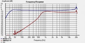
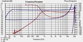
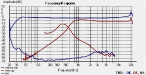
Blue cruve is the control on V1. red is V2
first image is freq response, second freq response and phase, 3rd is freq response and THD
adding the resistor over cap, does not do anything execpt lower my corssover. distortion still there. i used 15 Ohm and later a 30 wich does not do much either
for the fun of it ill record a piece of piano on v1 and v2, the 100 sine maybe better a 500 ? sine caus the crossover shifted few hundred
i know have connected the line out of the amp to my laptop mic in, without boost. and ran homlimpulse.
the frequency for the crossover is shifted due impedance of the line in i think.
Blue cruve is the control on V1. red is V2
first image is freq response, second freq response and phase, 3rd is freq response and THD
adding the resistor over cap, does not do anything execpt lower my corssover. distortion still there. i used 15 Ohm and later a 30 wich does not do much either
for the fun of it ill record a piece of piano on v1 and v2
, the 100 sine maybe better a 500 ? sine caus the crossover shifted few hundredAttachments
Last edited:
here a sample of piano.
played by laptop, to amp wich is connected to the esl with the cap. the left channel is recorder after the cap, and the right channel before the cap.
so left V1 right V2
https://skydrive.live.com/embed?cid=661B00CA82FBAA7D&resid=661B00CA82FBAA7D%21202&authkey=AI6sbUITNVkxcB8
ofcourse nooise llevel is pretty high with all these amps in between , and ofc the input from laptop etc. but the diference is clear. bad and really bad.
volume was set pretty low to not demolish my laptop and second amp input
here a sample of piano.
played by laptop, to amp wich is connected to the esl with the cap. the left channel is recorder after the cap, and the right channel before the cap.
so left V1 right V2
https://skydrive.live.com/embed?cid=...I6sbUITNVkxcB8
ofcourse nooise llevel is pretty high with all these amps in between , and ofc the input from laptop etc. but the diference is clear. bad and really bad.
volume was set pretty low to not demolish my laptop and second amp input
made mistake there left is V2 right V1
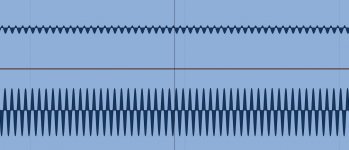
ofcourseHere is a picture wat happens i think.
is a screenshot taken in protools of a sweep i played with and without cap. upper is with lower is without , (V1 bot V2 top)
as seen it has problems to get positive. it folows the control nicely in the negative but crap in the positive.
also is out of phase as you can see,but thats explained by the phase measurement, the picture is from a frequency somehwere in the crossover range, where the signal is out of phase as you can seee in the holmimpulse measurement. so thats ok
, only thin not ok is the fact that positive and negative ar not equal.Attachments
Last edited:
if i remove the panels from the trannie, when playing the distortion stays the same on the headphone. when i remove the trannie from the cap, distortion on the headphone disapeares. so in my conclussion it has to be the trannie. but only thing i still dont get is why all of this disapeares with higher volume. i might have to install my class a amplifier to see if this makes any diference in maybe current/voltage drive capabilitys. expecially on low volumes. ..... hate to move this thing
well that did not help either.... ok im out of ideas. if its the tranie, then i have like 6 none working tranies, wich do work without cap...... kind of wierd a.
only thing i can do now is get bigger cap just to not pump in allot of power in the tranies under the resonance frequency, en damp the hump around 200 Hz with felt. i believe i can almost entirely remove it with this stuff on the back. that leaves me with a rolloff of 18dB octave at 220 hz, maybe cross the magnepan there with an 18dB oct filter ?
Last edited:
if i remove the panels from the trannie, when playing the distortion stays the same on the headphone. when i remove the trannie from the cap, distortion on the headphone disappears. so in my conclusion it has to be the trannie. but only thing i still don't get is why all of this disappears with higher volume.
Excellent trouble shooting

Looks like you have isolated the cause of the distortion to the transformer.
Perhaps the cores are not of best quality for audio use and retain a small amount of residual magnetism in one direction. Putting the capacitor in series keeps the amplifier from being able to control the residual magnetism at zero crossing.
Can you post a picture, part number or link for your transformer?
If you prefer to keep using these transformers, probably the best solution is to use without a series capacitor and an active crossover.
dont have any serial or part number there from solosound electrostatic speakers. have pretty good rep, they used this particulair model with active crossover so..... but there from 1975 ofr something so cant find any onfo on those thats for sure. im trying right now with way bigger cap and dampening.. look kind of promissing. but one last thing how tdo i measure them proper. caus to close wil give a good result whats happening with dampening but further away the bass drops ofcourse since theres no proximity. but when i measure further away i get really nasty graphs. humps and stuff specially in the 200 to 500 range. not sure if its the room or furniture or ground reflexioins etc.
there from solosound electrostatic speakers. have pretty good rep, they used this particulair model with active crossover so..... but there from 1975 ofr something so cant find any onfo on those thats for sure. im trying right now with way bigger cap and dampening.. look kind of promissing. but one last thing how tdo i measure them proper. caus to close wil give a good result whats happening with dampening but further away the bass drops ofcourse since theres no proximity. but when i measure further away i get really nasty graphs. humps and stuff specially in the 200 to 500 range. not sure if its the room or furniture or ground reflexioins etc.made mistake there left is V2 right V1
Here is a picture wat happens i think.
is a screenshot taken in protools of a sweep i played with and without cap. upper is with lower is without , (V1 bot V2 top)
as seen it has problems to get positive. it folows the control nicely in the negative but crap in the positive.
also is out of phase as you can see,but thats explained by the phase measurement, the picture is from a frequency somehwere in the crossover range, where the signal is out of phase as you can seee in the holmimpulse measurement. so thats ok
What I can see it's a definite DC offset most likely at the amp's output (??). Do you have mutimeter/voltmeter of any kind?
Last edited:
if i remove the panels from the trannie, when playing the distortion stays the same on the headphone.
When you removed the panels and still heard the distortion at V2 but not V1, was the HV bias supply still connected to the transformer? or did you disconnect it from the transformer when you removed the panel connections.
V2 is sampled after the signal has passed thru the 15uF capacitor so even if the amp did have some DC offset, the capacitor should effectively remove it I would think.What I can see it's a definite DC offset most likely at the amp's output (??)
I'm still trying to come up with a reason for this type of distortion at V2 but not at V1...something very odd is going on.
I keep thinking there is something we are missing.
Last edited:
What I can see it's a definite DC offset most likely at the amp's output (??). Do you have mutimeter/voltmeter of any kind?
i have a simple multimeter. but that means 3 of my amps have this ?
, and what can i do to check ?
When you removed the panels and still heard the distortion at V2 but not V1, was the HV bias supply still connected to the transformer? or did you disconnect it from the transformer when you removed the panel connections.
i kind have to admit i think i did not disconected the 0 from the tranie to bias, because i thought without the 2 stators its not a capacitor anymore. i did disconnect the bias from the wall socket to see if anything changed on the headphones. but ofc nothing happend.
Last edited:
You need to know what alloy it is made of. A photo won't help.sorry i really have no idea. im not really into transformers
For this kind of application, where the magnetizing inductance of the transformer plays a big role, a very low coercivity material is essential, otherwise it will cause the kind of problem you notice.
As a temporary fix and to confirm the effect, you could mix your low level audio with a high level ultrasonic frequency (>20KHz more or less, depending on your hearing abilities).
...For this kind of application, where the magnetizing inductance of the transformer plays a big role, a very low coercivity material is essential, otherwise it will cause the kind of problem you notice...
It seems that most core related distortion mechanisms, including that due to DC offset or residual magnetism that I had suggested, result in distortion that gets worse with increasing volume which does not match the symptom described by WrineX.
Rereading the post by Elvee the comment about inductance playing a big role suggested to me a possible mechanism for the distortion. The inductance of the primary and the series capacitor form a voltage divider. The larger the primary inductance, the larger the portion of the input voltage that will be present across the primary.
Now, the primary inductance of all iron core transformers is a function of the number of turns and the permeability of the core. The permeability of the core is a function of the input voltage, increasing from some initial value of usually several 1000 and peaking just before core saturation starts. This results in the primary inductance portion of the voltage divider being a function of the input voltage. Usually the primary inductance is large enough that it's impedance is significantly larger than that of the series capacitor.
But poor transformer iron has very low initial permeability and would result in very low primary inductance for low input voltages. So, only a small portion of the input voltage appears across the primary. This also means that the majority of the voltage drop due to any current distortion caused by the core will show up across the capacitor and distort the voltage fed to the primary. As voltage amplitude increases, the primary inductance increases and a greater portion of the input voltage will appear across the primary and distortion is reduced.
The fix is to use better core material, or drive the transformer from a lower impedance source (ie no series impedance like capacitor)
Yes, in short it is caused by the non-zero coercivity resulting in hysteresis and causing distortion, just like in raw magnetic recording.Rereading the post by Elvee the comment about inductance playing a big role suggested to me a possible mechanism for the distortion. The inductance of the primary and the series capacitor form a voltage divider. The larger the primary inductance, the larger the portion of the input voltage that will be present across the primary.
Now, the primary inductance of all iron core transformers is a function of the number of turns and the permeability of the core. The permeability of the core is a function of the input voltage, increasing from some initial value of usually several 1000 and peaking just before core saturation starts. This results in the primary inductance portion of the voltage divider being a function of the input voltage. Usually the primary inductance is large enough that it's impedance is significantly larger than that of the series capacitor.
But poor transformer iron has very low initial permeability and would result in very low primary inductance for low input voltages. So, only a small portion of the input voltage appears across the primary. This also means that the majority of the voltage drop due to any current distortion caused by the core will show up across the capacitor and distort the voltage fed to the primary. As voltage amplitude increases, the primary inductance increases and a greater portion of the input voltage will appear across the primary and distortion is reduced.
The fix is to use better core material, or drive the transformer from a lower impedance source (ie no series impedance like capacitor)
The fix, temporary or definitive, could be the same: add a high frequency bias.
Before jumping to conclusions, you should confirm the core material is actually the cause of your problems, otherwise you could spend money for nothingWow thx for the so long rePly and help , so in the end , they suck
- Status
- This old topic is closed. If you want to reopen this topic, contact a moderator using the "Report Post" button.
- Home
- Loudspeakers
- Planars & Exotics
- distortion From ESL at low level