Hi Miklos,
I'm talking about changing the power supply a little to reduce charging spikes. Add some resistance between the rectifiers and the capacitors. It will drop some voltage (good) and filter out the hash (also good) and greatly reduce the peak charging currents. The end result is that everything runs a little cooler.
I have some of those here as well. I haven't had a chance to try this on a THD analyzer, but the concept works on audio equipment.
-Chris
Try bypassing that 1 ohm resistor and see where the noise and distortion goes.
My finding with my oscillator is as little as 1 ohm in series with ground enough to raise the noise 40dB.
Hi David,
I tried to separate the two chassis and shorted out the 1 Ohm resistor series with the output ground, but didn't do much. My bench environment is just to messy , the power ground looks like missing. I'm digging in the basement now for an insulation transformer ,and will try to float most of the instruments.
Hi Miklos
First Connect an external +/- 30 volt PS to the rear panel connectors and repeat the FFT PS tests. This will tell you what the best improvement you will get. You may wish to run an FFT test on the external PS also.
The meter / monitor circuit could be modified to remove the rectifier distortion components.
Note: Some versions of the 334A don't have the 3 Bananas external connectors on the rear panel. The power PCB has the protection diodes. You could add the Bananas connectors or another type connector. The other thing is to BRIDGE the 200uf caps common's as the PCB edge connector could be a problem contacts and some form of half wave rectification can cause some problems.
Attach the new FFT files. Good hunting Duke
Hi Audio1man,
I would like to test with the external DC supply, but that means I have to get a bunch of batteries to make up the required 2x30V. I moded the A1 board by installing two 15V regulators for the eventual Op Amp mod, and I noticed the CR5 and CR6 diodes on the board, and you right they not connected to anything. If I would have the batteries I would install the DC connectors to the rear. The noise on the +-25 Rails are less then a mV now. The 200uF's on my A1 board was 500uF (now 470) and the bridging is already on the PCB.
I would like to know about the meter amp mod, elimination of the diodes in the audio path.
Thanks.
Attachments
Hi Miklos,
I'm talking about changing the power supply a little to reduce charging spikes. Add some resistance between the rectifiers and the capacitors. It will drop some voltage (good) and filter out the hash (also good) and greatly reduce the peak charging currents. The end result is that everything runs a little cooler.
I have some of those here as well. I haven't had a chance to try this on a THD analyzer, but the concept works on audio equipment.
-Chris
Hi Chris,
I also used to do that in power amps, to dampen the top off conduction of the rectifiers. I will try to implement it here to.
I would recommend the Panasonic VP-7722A.
There are a few on eBay now.
THx-RNMarsh
Thanks, but just a bit to expensive for me
")
The nice FM signal generators are just down that list some too.
-Chris
Not much future in them, if the whole world will go digital.
I makes me sad, I have least 10 very good FM tuners.
First the distraction of the programming/broadcast quality and than going to digital. That will end the fun in FM radio.
Hi Miklos
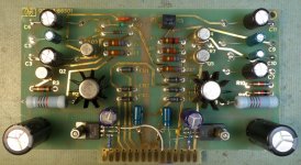
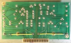
I see that the PCB routing is much better that the schematic shows. The schematic lead me to suspect that charging currents could be a problem. You should add some insulation under leads from C5, C6 and C10. When I replace Axial Caps with Radial I lay them down and add some glue to them.
What does the FFT look like with the modified PS?
Good work Duke
Hi Miklos
I see that the PCB routing is much better that the schematic shows. The schematic lead me to suspect that charging currents could be a problem. You should add some insulation under leads from C5, C6 and C10. When I replace Axial Caps with Radial I lay them down and add some glue to them.
What does the FFT look like with the modified PS?
Good work Duke
Hi Audio1Man,
Thanks. The result so far in #454, still looks bad, but I think (or hope) the bulk of the hum coming from my measurement setup. I do the gluing of the caps to, mostly with silicon rubber, but these ones are steady without the gluing.
Keep in mind how far below the original spec you may be trying for. After a point you run into design issues that may never have been addressed in the original design. Its possible your getting some transformer radiation into the ground system for example. It might never have been an issue when .01% was SOTA. but looking at .0001% levels its now a real issue. A quich check on the transformer/unregulated supply side as a noise source would be to lower the AC voltage looking at the hum products. If they change with level but remain mostly constant in spectrum is the transformer mostly. If they change a lot (like the currents in the regulator) it may be a grounding issue. sometimes a simple rerouting of a ground can make a big difference. I reduced the AC modulation in a crystal oscillator by rerouting a ground to the other side of the transformer preventing it from picking up the transformer field. However eventually you hit a wall. That's when you need to let go. I have several of those dead ends I get stuck on occasionally, until I realize they are dead ends.
Noises and grounding.
After a found an old Philips transformer from the movie theater business times and attached some cables and connectors to it, which is now floating the 334a , but no ground yet. Here are the two measurements from the +-25V supply. The computer is not yet floating, but I have now the ability to float that to.
Looks much better now.
Attachments
Hi Miklos
Good work. This look's about 20-25dB better. I think that some more improvement could be made. The COMMON TX lead and other common many be sharing the charging currents. I don't have the wiring diagram only the schematic. If you look @ both ps you can see some minor differences in each and this means you have some minor unbalance in the layout.
You should retry your test as in #454 and see if it is usable.
Duke
Last edited:
Retest.
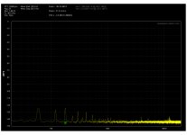
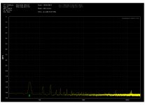
I made some new measurements, overall not much improvement on the output.
Also it looks like my Victor oscillator distortion is quite high for this work.
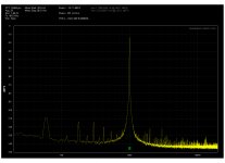
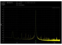
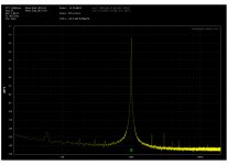
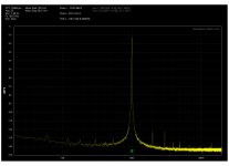
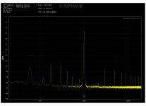
After the floating now the HP334a ,things improved a bit, I added the oscillator to, it is now floating on the same transformer, but on a different coil, so it's galvanically insulated from the 334a. That helped the impedance converter stage at C14, but not the rest of the unit. I tried to separate the outer and inner chassis ground, and tried to take the ground for the output from the input. Non of them helped. I can't make testing inside, since I had to put back the top cover. THD is to high after the Meter circuit in all three modes. The pictures from the left are:
Victors oscillator,
334a Noise at c14,
334a Noise at c14 - 334a on AC filter,
334a Noise at c14 - 334a on filter - Victor PS on insulated AC, and
334a Noise at the Output - 334a on filter - Victor PS on insulated AC.jpg
I made some new measurements, overall not much improvement on the output.
Also it looks like my Victor oscillator distortion is quite high for this work.
After the floating now the HP334a ,things improved a bit, I added the oscillator to, it is now floating on the same transformer, but on a different coil, so it's galvanically insulated from the 334a. That helped the impedance converter stage at C14, but not the rest of the unit. I tried to separate the outer and inner chassis ground, and tried to take the ground for the output from the input. Non of them helped. I can't make testing inside, since I had to put back the top cover. THD is to high after the Meter circuit in all three modes. The pictures from the left are:
Victors oscillator,
334a Noise at c14,
334a Noise at c14 - 334a on AC filter,
334a Noise at c14 - 334a on filter - Victor PS on insulated AC, and
334a Noise at the Output - 334a on filter - Victor PS on insulated AC.jpg
Attachments
-
 334a Noise at c14 334a on filter.jpg321.4 KB · Views: 163
 -
 334a Noise at c14.jpg327.5 KB · Views: 168
 -
 Victor.jpg305.8 KB · Views: 174
 -
 334a Noise at c14 334a on filter - Victor PS on insulated AC.jpg305 KB · Views: 69
 -
 334a Noise at Output - 334a on filter - Victor PS on insulated AC.jpg315.2 KB · Views: 64
Place your Victor oscillator into your QA directly. You are picking up noise from the 334a. Like 1Audio said above, you may be at the dead end of performance of the 334a. Victor's oscillator is way better than what the 334a can measure.
Using the 334a for the front end of a power amp in higher distortion may work because the amp will be noisier than the 334a. However, a simple passive resistive divider would work just the same or even better.
Using the 334a for the front end of a power amp in higher distortion may work because the amp will be noisier than the 334a. However, a simple passive resistive divider would work just the same or even better.
Place your Victor oscillator into your QA directly. You are picking up noise from the 334a. Like 1Audio said above, you may be at the dead end of performance of the 334a. Victor's oscillator is way better than what the 334a can measure.
Using the 334a for the front end of a power amp in higher distortion may work because the amp will be noisier than the 334a. However, a simple passive resistive divider would work just the same or even better.
I mentioned in #443 that I don't have the ambition to do a better job than Richard Moore did. I wanted to use the 334a as an input front end to the QA400 with attenuator and an indicator of the input voltage, not as a distortion magnifier. What you asking for the "Victor oscillator into your QA directly" is the first picture above, and the 334a's impedance converter at the cap C14 is the fourth picture in the same reply. The difference between my Victors oscillator and it's signal going through the 334a's impedance converter is THD +1.3dB. Not much if you asking me. What is left for me to achieve my goal is to reduce the distortion of the 334a's meter amplifier.
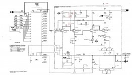
Meter amp.
This is the circuit I would like to improve on or replace. It has +40dB gain and a load of distortion. On the top off it the puzzle is the excess hum, which is not present in the impedance converter, but the attenuator takes off 40dB and the meter amp is the one which restore it, and in the Voltmeter function send it to the 334a output, where the QA400 would be.
This is the circuit I would like to improve on or replace. It has +40dB gain and a load of distortion. On the top off it the puzzle is the excess hum, which is not present in the impedance converter, but the attenuator takes off 40dB and the meter amp is the one which restore it, and in the Voltmeter function send it to the 334a output, where the QA400 would be.
Attachments
This is the circuit I would like to improve on or replace. It has +40dB gain and a load of distortion. On the top off it the puzzle is the excess hum, which is not present in the impedance converter, but the attenuator takes off 40dB and the meter amp is the one which restore it, and in the Voltmeter function send it to the 334a output, where the QA400 would be.
Not surprised the noise is high from this amplifier. Any op amp will do better.
Hi miklos,
Can you pick off the signal before the meter amp and use that? This circuit was conceived to drive the meter, and not much thought would have gone into having a spectrum analyzer hanging on that output. I suspect that HP's spectrum and network analyzers would be used directly as they have far greater performance than the 334A
I have one as well that I'll be diving into some day. I'm not above replacing some circuitry as long as I can keep the high bandwidth the 334A is capable of.
-Chris
- Status
- This old topic is closed. If you want to reopen this topic, contact a moderator using the "Report Post" button.
- Home
- Design & Build
- Equipment & Tools
- distortion analyzer recomendations?