yes, i would think so, since the seller confirmed me that the 1700B model has a switch on the back for the 220V.
I set the price for the 1700B at $150 which is an half of what the seller of the 1710 is aking for.
I' m sure that the 1710 is a better and more performant unit but i wouldn't like to spend right away $300 for a distortion analyzer since i have never used one...and i would like to learn first and......and if... i 'll became an "expert"... and feel the need for something better....then buy a better analyzer like yours (boonton).
In the meantime, would it be possible for you give me some good hints on how and what to ask to the seller to make sure that the analyzer is working?
hope i'm not bothering you with all this questions.
Thanks in advance.
IIRC, the ST 1710 was designed for tape decks. Do you mean ST 1701A?
I recalibrated/restored the Distortion Analyzer section to .0015% THD @ 1KHz to meet original specs listed in the Service Manual.
Hi jblmar,
Surely the lowest frequency isn't 900 KHz?
So is it a 10 Hz - 1.5 GHz, or 9 KHz to 1.5 GHz? The problem with inexpensive spectrum analyzers is the number of points it logs per sweep, and the vertical resolution. You should check to see how low the noise floor is before you buy.
I use my audio spec-an (HP 35665A Signal Analyzer) on the output of the distortion analyzer (HP 339A). Not the best combination by a long shot, but at least I can see what the meter is measuring. So your Rigol might work very well doing the same thing.
-Chris
Use of the HP-334a.
Hello,
I have a HP-334A in perfect shape in and out.
I would like to use it in connection with my QA400.
I read all it can be read on Diyaudio and on Richard Moore's web page "Greening the HP-334a" so I know it is an impossible task to get the distortion down, to be able to use it as a distortion range extension to the QA400.
The complains what I picked up was:
1. To high meter amp distortion on the A2 board (disconnecting the meter would have a positive effect).
2. To high impedance of the Wien bridge, picking up noise.
3. Distortion of the Rejection Amp,
4. and the Auto Nulling circuit (disconnecting the lamps has a positive effect on the distortion).
5. Grounding problems.
6. Possible problems with the impedance converter.
7. Power Supply
I would ask the followings, if somebody would be nice to answer:
Could I use the unit as a front end to my QA400?
It has some nice weight to it so the cables wouldn't yank it of the table, plus a attenuator and a meter. That would be very convenient, seeing what voltage I am dealing with and it would protect the QA400 input.
I recaped the Impedance converter and the PS, all the 50 years old electrolytes are gone from there now. This improved the Impedance converter THD, from -93dB to just above -105dB, measured with Victors 1kHz oscillator , the output to the QA400 taken from A2/C14. I tried some polyester (other types wouldn't fit) film cap on the position A2/C4, and readjusted the Bias for Q1 (was almost dead on), non of them helped more. Would that be good enough, or should try to replace the Imp. Conv. circuit with an Opamp?
I would leave the Meter Amp alone (it's working) would make a 40dB gain Opamp circuit and drive it from the Meter Amp input A2/C15 (#6 attenuator output), disconnect the 334A output from the meter amp A2/#12 connection and use it for Opamp circuit output.
I like to do this for starters, maybe more later.
Thanks.
Hi miklos,
You should be able to hang the QA400 on the output terminals, but it would output it's own problems as well. Having said that, it would make a bullet proof front end, and you have probably noticed that the meter is deadly accurate.
So what can you see in the output as your biggest problem? Distortion from the 334A, or noise?
-Chris
I just became very close with the 334a I picked up. I used the outputs to feed my spectrum analyzer and Arta. It is a great front end, but it raises the noise floor. My passive divider has much less noise. I have not recapped anything on my 334 yet.
Also, you can't disconnect the meter from the circuit. The meter is part of the circuit and the theory in the manual explains some detail of the bridge / meter circuit.
Grab some comparison screen shot of your signal through a divider vs through the 334. Not sure if the QA allows you to have multiple traces saved on the screen.
I worked with Richard Moore on greening the 334A. He would have given up a year sooner if it wasn't me encouraging he to keep going.
The 334A was suitable for it's time and later replaced with lower distortion lower noise units like the 339A. In the seventies there was no hope to ever go beyond 0.0001%.
Look what we have today. Where will we be in another 20 years. If I live so long.
The 334A was suitable for it's time and later replaced with lower distortion lower noise units like the 339A. In the seventies there was no hope to ever go beyond 0.0001%.
Look what we have today. Where will we be in another 20 years. If I live so long.
Impedance converter.
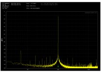
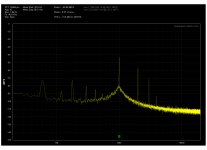
My Impedance converter spectrum looks like this, after replacement of the caps in it and in the PS. I'm an amateur and have a hard time to analyze circuits, but isn't this a very good result? Question is if it good enough for the QA400, and if is not how to improve it. Measurement was made after A2/C14.
My Impedance converter spectrum looks like this, after replacement of the caps in it and in the PS. I'm an amateur and have a hard time to analyze circuits, but isn't this a very good result? Question is if it good enough for the QA400, and if is not how to improve it. Measurement was made after A2/C14.
Attachments
Last edited:
Distortion mode.
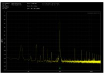
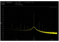
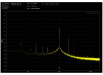
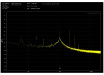
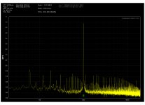
These are the output spectrum's in Distortion mode, first -50dB manual. then -50, 60 and -70dB in auto. In manual I couldn't go bellow -50dB. Looks like the attenuator working well, but the distortion is to high.
These are the output spectrum's in Distortion mode, first -50dB manual. then -50, 60 and -70dB in auto. In manual I couldn't go bellow -50dB. Looks like the attenuator working well, but the distortion is to high.
Attachments
-
 HP334a - Distortion Manual -50dB - in 310mV - Output - Victors.jpg321.2 KB · Views: 239
 -
 HP334a - Distortion Auto -50dB - in 310mV - Output - Victors.jpg319.7 KB · Views: 221
 -
 HP334a - Distortion Auto -60dB - in 310mV - Output - Victors.jpg315.3 KB · Views: 203
 -
 HP334a - Distortion Auto -70dB - in 310mV - Output - Victors.jpg317.1 KB · Views: 56
Thanks for all of you who took the trouble to reply.
I don't want to disconnect the meter, in fact I will leave the meter amp alone, and was thinking to use an alternate +40dB opamp circuit for the distortion measurement instead the original, and use the meter amp just for the meter. Would that work?
I don't want to disconnect the meter, in fact I will leave the meter amp alone, and was thinking to use an alternate +40dB opamp circuit for the distortion measurement instead the original, and use the meter amp just for the meter. Would that work?
This is the output of the 334a in voltmeter mode 310mV in.
I had to replace the 1 Ohm resistor in the output connector ground, it was burned.
Try bypassing that 1 ohm resistor and see where the noise and distortion goes.
My finding with my oscillator is as little as 1 ohm in series with ground enough to raise the noise 40dB.
PS noise.
Hi Chris,
Yes, I will work further on the PS, but look how was it before the recap, all that harmonics coming from the PS. After the recap the 120Hz hum is quite low, so what is in the second picture looks like capacitive coupled , and in part coming from my cabling setup and equipment grounding problems. These are after A2/C14.
Attachments

Miklos I can't remember if HP did a double chassis in the 334A.
If so then the inner chassis should be floating and only the outer should be earth grounded.
There may coupling caps for ground to ground and this coupling cap or pas make a big difference to ground noise.
In the Shibasoku 725 if the cap between the chassis' is lifted the ground noise rises 30dB.
Check the cap for leakage, if it exist. If not then try adding one and see what happens.
1nF to 10nf.
See the 339A manual for guidance.
Getting noise down is like peeling an onion. Just because something tried appears to have no effect doesn't mean it isn't effective. It might mean the noise level of the 334a is too high to to see the effect.
Miklos, if u have not studied the manual, give it a good read. Great theory of operation. I would suggest going through the verification procedure as well make sure your unit is working up to its specs. Also, look at the calibration procedure. Your manual nulling and auto nulling should match.
I created a test signal using a large fundamental sine wave and then a small harmonic sine wave. This allowed me to measure 10, 1 .1 and .01 % distortion with the 334 and validating it with another analyzer and software (Arta).
With complex distortion and lots of harmonics, I found the meter reads more like and average response and not RMS. The manual touches on this a bit with a statement about 'harmonic correction factor'. It is not very detailed.
Keep up the good work.
Grounding.
Hi David,
Yes, it has the floating inner chassis and in the manual shows the connection between the outer and the inner one. It was also mentioned by R. Moore the "Greening the HP-334A" page. The schematic detail shows it close to the input connector, where one is able to bridge it or not. The schema is the same as used by many amplifiers 1M and a cap parallel with it. I have to look physically the actual cap, it is marked as C2/1 where the 1 would be what capacitance ? I will try the removal of the bridge, or the L3.
Miklos I can't remember if HP did a double chassis in the 334A.
If so then the inner chassis should be floating and only the outer should be earth grounded.
There may coupling caps for ground to ground and this coupling cap or pas make a big difference to ground noise.
In the Shibasoku 725 if the cap between the chassis' is lifted the ground noise rises 30dB.
Check the cap for leakage, if it exist. If not then try adding one and see what happens.
1nF to 10nf.
See the 339A manual for guidance.
Getting noise down is like peeling an onion. Just because something tried appears to have no effect doesn't mean it isn't effective. It might mean the noise level of the 334a is too high to to see the effect.
Hi David,
Yes, it has the floating inner chassis and in the manual shows the connection between the outer and the inner one. It was also mentioned by R. Moore the "Greening the HP-334A" page. The schematic detail shows it close to the input connector, where one is able to bridge it or not. The schema is the same as used by many amplifiers 1M and a cap parallel with it. I have to look physically the actual cap, it is marked as C2/1 where the 1 would be what capacitance ? I will try the removal of the bridge, or the L3.
Attachments

Miklos, if u have not studied the manual, give it a good read. Great theory of operation. I would suggest going through the verification procedure as well make sure your unit is working up to its specs. Also, look at the calibration procedure. Your manual nulling and auto nulling should match.
I created a test signal using a large fundamental sine wave and then a small harmonic sine wave. This allowed me to measure 10, 1 .1 and .01 % distortion with the 334 and validating it with another analyzer and software (Arta).
With complex distortion and lots of harmonics, I found the meter reads more like and average response and not RMS. The manual touches on this a bit with a statement about 'harmonic correction factor'. It is not very detailed.
Keep up the good work.
Hi skidave,
Thanks for the advise. I have the manuals and read almost everything available here on Diyaudio. I will look into the manual/auto tuning issue , good to know that it suppose to work the same. I don't want to overwhelm my self with the tasks, so first I would like to work on the distortion and noise issue, and then step by step the rest.
PS HUM
Hi Miklos
First Connect an external +/- 30 volt PS to the rear panel connectors and repeat the FFT PS tests. This will tell you what the best improvement you will get. You may wish to run an FFT test on the external PS also.
The meter / monitor circuit could be modified to remove the rectifier distortion components.
Note: Some versions of the 334A don't have the 3 Bananas external connectors on the rear panel. The power PCB has the protection diodes. You could add the Bananas connectors or another type connector. The other thing is to BRIDGE the 200uf caps common's as the PCB edge connector could be a problem contacts and some form of half wave rectification can cause some problems.
Attach the new FFT files. Good hunting Duke")
Hi Chris,
Yes, I will work further on the PS, but look how was it before the recap, all that harmonics coming from the PS. After the recap the 120Hz hum is quite low, so what is in the second picture looks like capacitive coupled , and in part coming from my cabling setup and equipment grounding problems. These are after A2/C14.
Hi Miklos
First Connect an external +/- 30 volt PS to the rear panel connectors and repeat the FFT PS tests. This will tell you what the best improvement you will get. You may wish to run an FFT test on the external PS also.
The meter / monitor circuit could be modified to remove the rectifier distortion components.
Note: Some versions of the 334A don't have the 3 Bananas external connectors on the rear panel. The power PCB has the protection diodes. You could add the Bananas connectors or another type connector. The other thing is to BRIDGE the 200uf caps common's as the PCB edge connector could be a problem contacts and some form of half wave rectification can cause some problems.
Attach the new FFT files. Good hunting Duke
Last edited:
- Status
- This old topic is closed. If you want to reopen this topic, contact a moderator using the "Report Post" button.
- Home
- Design & Build
- Equipment & Tools
- distortion analyzer recomendations?