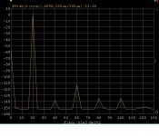
Measurement was at 1KHz.
The big problem with this device is power dissipation. If you keep the JFET around Idss, Vce of the cascode device should be under 10V. ~100mW is all this SMD case can take. The Vcemax of 50V is pretty much useless.
Devices from the same tube (I got 100 pcs and fed my whole class) are matched to +/- 10%, so a cascoded LTP is feasible. I've built a discrete opamp with these devices in the input stage, 18 more transistors and 0402 RC's (everything hand soldered) in less than .25 sq. in.
Edit: 1KHz and about 12mA (that is, Idss)
Thanks! Better you and your students than me, hand soldering 0402!
If the construction is similar to other SMD JFETs, the gate lead has high thermal conductivity to the chip. Although it's not particularly convenient to provide a lot of local copper in the plane, one could go up. I'll let everyone know how my multiple 862 birds-on-a-wire construction works out. The small irony is the tempco is so low that a temperature estimate may prove difficult
")
Granted I will match the BF862 jfets as carefully as I can but why can't there be a dc balance tweek up front around that diff amp. ! Ray
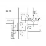
No penalty at all, you can make one of those 60 Ohm resistors trimmable (100 Ohm pot) and trim offset there. The easiest offset trim would be a large-ish pot across the two lower current mirror devices with the wiper to Vee. The pot is out of the signal path totally, in fact the other one would be too.
For amusement value both trims can be used together to trim offset to 0 and the Aol to essentially infinite.
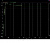
A quick look at jcx's idea. This is not definitive but what I see looks good. As stated before there is a long settling tail but for a line amp or preamp this should not matter. Seconds are now essentially gone, this is 600 Ohms at 20V p-p and 20kHz.
Attachments
Last edited:
I'm tempted to try that, but I'll probably start with rudimentary matches. I'm especially keen to see if I can parallel these parts without oscillation. But bear in mind that I have other applications for the paralleled parts --- I'm not at this point so interested in building this particular amplifier, but happy to watch. One such app is as the primary devices in a modification of the linuxguru unity-gain buffer, and the first I will do only requires 2 862 in parallel per buffer. For some preamp apps I may use as many as 8 or 10, and for an envisioned direct ribbon mic preamp, quite a few moreHello Brad
With the parallel jfets are you planning not to match the parts in the diff stage and just see how it works out, or have I misunderstood you.
Regards
Arthur
I have about 200 pieces to play with, certainly beyond limits of time and patience, but I'll probably measure some more before tearing the jig down. What I really ought to do is throw things into excel and do some fancier statistics, like trying to detect if they are really Gaussian-distributed, or are things multimodal etc.
I may measure gate leakage to guess at chip temperatures. It would be really nice if the wire heatsink approach allows higher dissipations, even though these parts work well with low Vds. Cordell, in Linear Audio Vol. 4, has shown an MC preamp design with individual LSK389 pairs and individual associated current sources, and some resistance in the drains. Although not quite as fast as the 862 the LSK389s are fast enough to occasion RF oscillations too, so it is interesting that apparently no extra parts in series with the gates were required for stability.
I'm tempted to try that, but I'll probably start with rudimentary matches. I'm especially keen to see if I can parallel these parts without oscillation. .
The BF862 in my experience can not go beyond 4 paralleled devices with even good DIY assembly. SMD ferrite beads or inductors on each group of 4 (gates) have no noise penalty.
The BF862 in my experience can not go beyond 4 paralleled devices with even good DIY assembly. SMD ferrite beads or inductors on each group of 4 (gates) have no noise penalty.
Also, gate stopper resistors may be used. Since there is virtually no current to the gates, there shouldn't be any noise penalty.
This guy seems to get away with 8 in parallel.The BF862 in my experience can not go beyond 4 paralleled devices with even good DIY assembly. SMD ferrite beads or inductors on each group of 4 (gates) have no noise penalty.
Hand solder 0402 parts? - That's hard! Brad Plunkett made me do it a few times
This guy seems to get away with 8 in parallel.
Hand solder 0402 parts? - That's hard! Brad Plunkett made me do it a few times
It gets touchy, the small inductors are harmless.
They will add series (i.e., voltage) noise. It is true though that there will not be any additional noise due to parallel noise, as there would be with substantial bipolar base current.Also, gate stopper resistors may be used. Since there is virtually no current to the gates, there shouldn't be any noise penalty.
Samuel Groner recently used some nominally 220nH parts in series with each gate for paralleled 862s on a PCB, but I'm not sure what their properties as RF resistors were. Another author shows 1uH, which seems perhaps a bit high.
Cordell's use of resistors in the drains (albeit with slower parts) is pretty much without a noise penalty. But whether those need to be larger for 862s I don't know.
2SK170 are slower, 2SJ74 even more so, and he also separates them in a fashion via the local series feedback.This guy seems to get away with 8 in parallel.
http://www.synaesthesia.ca/LNschematics.html#This is the first design I've seen that nearly equals my 1980 moving coil preamp at 0.28nV/rtHz. I used a giarnomous number (2) of active devices.
There's some interesting results when playing with how the offset is nulled. Going back to my extremely mismatched BF862s, I trimmed the DC by adjusting the source resistors, the predominating 2nd harmonic was worse by 3db compared to matched devices. So, in the sim I tried resetting these to the default 30R, and only adjusting the current source 60Rs to null output. Now, I get -94db 2nd, and -92db 3rd: nominally superior distortion figures, but of a different nature ...
Frank
Frank
Last edited:
Low Noise Design SchematicsThis is the first design I've seen that nearly equals my 1980 moving coil preamp at 0.28nV/rtHz. I used a giarnomous number (2) of active devices.
Which you would like to share with us?
_-_-bear
What is the take-away?
What is the take-away that could be applied to this all purpose OPA?
Low Noise Design SchematicsThis is the first design I've seen that nearly equals my 1980 moving coil preamp at 0.28nV/rtHz. I used a giarnomous number (2) of active devices.
What is the take-away that could be applied to this all purpose OPA?
Last edited:
Correction: I hadn't checked the quiescent output current, it varies as you null the DC out, via the input stage resistors. So both have to be trimmed, there is an interaction. The output stage was running too high a current, hence the better distortion figures -- once corrected, the 2nd and 3rd harmonic were both at -89dB. Meaning, very close to identical distortion with badly mismatched JFETs ...Now, I get -94db 2nd, and -92db 3rd: nominally superior distortion figures, but of a different nature ...
Frank
But, and a mighty big one, the offset is at the mercy of the BF862s. If perfectly matched, LTspice predicts an excellent DC null up to 75degC; above that temp the offset goes a-wandering; on the other hand, if using a severely mismatched pair, with gain of 100, the offset varies between -2.4V and 2.4V in the range 7deg to 47deg (default is 27deg)!
There's a bit more to it than that, I shall do some more exploring ...
One thing, this has been an excellent learning exercise for me - thanks to all ...
Frank
Last edited:
Low Noise Design Schematics This is the first design I've seen that nearly equals my 1980 moving coil preamp at 0.28nV/rtHz. I used a giarnomous number (2) of active devices.
None at all. Just my demo of what can be done if you have a clear idea of what's important for good sound and ignore all Golden Pinnae considerations.What is the take-away that could be applied to this all purpose OPA?
It's a specialist application, now only of interest to vinyl fanatics with low output moving coil cartridges. Probably still the lowest noise such device in the known universe. It's taken more than 30 yrs for someone to come close. What Mr. synaesthesia tells me is that certain devices that I thought were Unobtainium may actually be available.
not an OPA
Congratulations on making a very low noise MC amplifier. -RNM
None at all. --- It's a specialist application, now only of interest to vinyl fanatics with low output moving coil cartridges.
Congratulations on making a very low noise MC amplifier. -RNM
- Home
- Source & Line
- Analog Line Level
- Discrete Opamp Open Design