fdegrove said:For SET amps there's no simple solution I know of, the endresult will invariably depend on whatever is in the signal path...
Unfortunately, it all is...
Hi Frank,
With the help of your phrasing .... what I was trying to say, admittedly cryptically, is that coupling tube stages in the manner contemplated by the DCMB circuit actually removes the power supply, in part, from the signal path. Here's an oversimplified illustration of what I see. Assume a simple CLC passive supply feeding an output tube. The tube conducts more heavily, current draw from the power supply increases, and that current increase causes a voltage drop across the impedance of the supply. That voltage drop is reduced, in part, by the action of the inductor and capacitors, which prop up the supply voltage. But neither the inductor nor the capacitors respond instantaneously, nor do they fully eliminate the voltage drop. Capacitors, for their part, suffer from dielectric absorption, to name just one of their limitations, preventing the capacitor from releasing 100% of its voltage charge. Inductors have their own problems. The overall result, in any event, is that any change in current drawn from the power supply necessarily results in an amusical modulation of the supply voltage by the very components designed to prevent those modulations.
That much is standard accepted knowledge. And as the story goes, those inevitable modulations flow through the plate load resistor or inductor to the grid of the next stage to there become indissolubly mixed with the music signal. Not an overall happy result. Replacing power supply capacitors with better varieties---better invariably meaning a capacitor with lower dielectric absorption---"cleans up" the music signal .... IMO, by reducing voltage modulations deriving from such things as dielectric absorption.
I think DCMB direct coupling actually prevents those modulations mixing with the music signal by coupling the supply to the cathode of the next stage. In this coupling method, modulations appear in same phase on both cathode and grid of the next stage, and cancel. The same-phase coupling renders the tube something of a differential amplifier so far as the power supply is concerned, amplifying only those AC components created across the plate resistor or inductor of the previous stage.
There is one hitch though. PSU modulations cancel only to the extent their voltage gradient on either side of the plate load resistor or inductor matches. Because PSU modulations reduce across that component as a percent that component represents to the overall resistance/reactance of the tube circuit, the question becomes how to best prevent such reduction. This issue was the subject of my previous post which concluded that inductive loading fares much worse in this regard.
Apart from that issue, the DCMB method of coupling actually removes power supply components from the signal path in the same manner, but not quite as effectively, as a differential tube stage. The DCMB method, though not as effective in performing this function, yet retains the comparative advantages of simplicity and single-tube operation, the latter being important for a variety of reasons, not the least of which is preserving a more pleasing harmonic spectrum.
Hi,
The idea is certainly appealing enough but...
Does this mean that non-ideal PS filtering components can now be used without them having a major impact on sonic performance of the amplifier?
Somehow I doubt this would be the case even though the idea seems very attractive...
I eagerly await the final listening results or are these out there somewhere already?
Cheers,")
The DCMB method, though not as effective in performing this function, yet retains the comparative advantages of simplicity and single-tube operation, the latter being important for a variety of reasons, not the least of which is preserving a more pleasing harmonic spectrum.
The idea is certainly appealing enough but...
Does this mean that non-ideal PS filtering components can now be used without them having a major impact on sonic performance of the amplifier?
Somehow I doubt this would be the case even though the idea seems very attractive...
I eagerly await the final listening results or are these out there somewhere already?
Cheers,
The idea is certainly appelaing enough but...
Does this mean that non-ideal PS filtering components can now be used without them having a major impact on sonic performance of the amplifier?
Somehow I doubt this would be the case ....
I doubt it also. From what I can see, the circuit suffers two limitations:
(1) for stages the output of which is coupled using this method, PSU noise is cancelled only imperfectly to perhaps a maximum 60%, depending on the anode resistor used, and
(2) for the output stage otherwise coupled (transformer coupled), PSU noise is not cancelled.
I eagerly await the final listening results or are these out there somewhere already?
A fellow in France has been building these amps for a few years and claims they hands down beat typical SE amps. I don't doubt his assessment given the several obvious advantages of this topology. I don't have a good guess how these advantages, and the limitations mentioned above, stack up against advantages and disadvantages of other topologies.
I think it's time to get off my butt and build one.

Well, I haven't built a DCMB amp yet (still gathering parts) .... but I've got that persistent itch for better sound, and feeling that itch was thinking about the noise reduction principles I think are at play in the DCMB topology. So I got to wondering if anything could be done with my two-stage 6SN7-572 SET without stacking the supplies (operating at 900 and 600VDC .... stacking would make me a bit nervous). Then it occurred to me that adding a single capacitor to the circuit might give part or most of what I perceive to be the noise reducing benefit of the DCMB topology. Here's the idea: capacitively couple the B+ of stage 1 (in my amp, the input/driver) to the cathode of stage 2 (in my amp, the output). B+ noise coupled as such appears on the cathode in-phase to B+ noise appearing on the grid---the two should cancel to the extent of any overlap in noise voltage magnitudes. In my set-up, the 6SN7 is loaded with a 67K resistor that drops about two-thirds of the B+. Two-thirds of the B+ AC noise is also dropped across the resistor, meaning an average of one-third of any noise on the driver B+ appears on the grid of the output tube. I say "average" because the actual amount of B+ noise appearing across the 6SN7 anode resistor, and thus on the output grid, varies as the tube's conductance changes.
My 572 output uses fixed bias and stands the cathode on two 10R resistors, one to each leg of the cathode paralleled to ground.
The 6SN7 is capacitor coupled to the 572 using a 0.5uF capacitor.
I placed a 1uF capacitor (same type as the grid capacitor) from the 6SN7 B+ to one leg of the cathode in one of the amps, and heard a quite noticeable decrease in noise (I'm listening mono, here, for the moment). Everything is clearer and *quieter,* especially the high frequencies, but including bass lines, vocal pitch, overall sense of rhythm, and to an extent larger than attainable by upgrading the power supply capacitors---I can say this to be true because I just finished upgrading power supply capacitors in the other amp with top grade capacitors ... The experience suggests to me that B+ noise is more pernicious than I previously thought. Wow.
A 1uF capacitor has a capacitive reactance at 1KHz of about 150 ohms, suggesting that, at that frequency, rather less than one-third of B+ noise voltage appears at the cathode, which is to say I think the betterment I heard can be increased by using a larger capacitor.
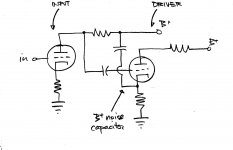
serengetiplains said:Here's a quick drawing of what I'm talking about.
This looks like an "ultrapath" or Western Electric style cathode bypass.
Have you seen this?:
http://www.nutshellhifi.com/library/Rosetta_Stone.html
In your connection the ratio of cancellation is set by the voltage drop of the B+ of your driver and output stages. In the WE circuit it is set by the ratio of the caps used for bypassing. Either way it looks pretty similar. Or am I missing something?
Jeff, I think two different principles are at play. WE coupling reroutes output tube return current through a high quality capacitor, effectively reducing the influence of the main power supply capacitors on the signal. The coupling I'm playing with is more akin to J. Broskie's Aikido circuitry, which uses in-phase noise signals in an overall differential topology.
Here's how I see this issue. B+ noise passes through the input tube anode resistor, mixes with the amplified music signal at that point and appears on the grid of the next stage, to there be amplified inextricably with the music signal for eventual presentation to one's ears. By placing the same noise signal *also* on the cathode of that second stage, and in phase, the noise effectively cancels because both grid and cathode are moving in phase with the noise---ie, the noise signal creates no grid-cathode voltage differential.
The ratio of cancellation, as I see it, doesn't reference voltage drop on the output tube supply, but is a product of matching noise voltages on grid and cathode of the tube otherwise amplifying the noise. Perfect matching cannot be attained.
serengetiplains said:WE coupling reroutes output tube return current through a high quality capacitor, effectively reducing the influence of the main power supply capacitors on the signal.
This isn't all the WE coupling does, at least not when combined with a typical cathode bypass capacitor. These two capacitors inject an amount of B+ noise into the cathode. The amount is set by the ratio of the capacitor values.
serengetiplains said:The ratio of cancellation, as I see it, doesn't reference voltage drop on the output tube supply,
What a lousy job of explaining I've done! I meant that the amount of noise injected into the cathode is dependent on the voltage drop (and the capacitor reactance, of course), not the cancellation.
serengetiplains said:Isn't that noise then amplified in-phase to the noise appearing across the output transformer to thus increase overall noise, or am I phase-confused?
See this:
http://db.audioasylum.com/cgi/m.mpl?forum=tubediy&n=11389
Ignore the part about the flaw (temporarily if you like.) The first paragraph describes how it works.
Look at it this way: isn't it the same phase as the power supply noise you are injecting from the driver B+ into the output stage cathode?
jeff mai said:Look at it this way: isn't it the same phase as the power supply noise you are injecting from the driver B+ into the output stage cathode?
If the driver and output are operating from the same supply, noise taken from the B+ near the output transformer (or from anywhere on the B+ rail) is, yes, in-phase to noise appearing from that same B+ (throught the driver load + coupling deviceson the output grid.
My confusion with your post arose from assuming that driver and output tubes had separate B+ supplies, per my diagram.
Hi,
Why would the type of plate load matter?
Resistor, CCS, inductor....The tube doesn't care.
Cheers,
Does an inductive loaded tube stage invert polarity?
Why would the type of plate load matter?
Resistor, CCS, inductor....The tube doesn't care.
Cheers,
serengetiplains said:Does an inductive loaded tube stage invert polarity?
Edit:
That is, driven by the grid?
A grounded cathode stage inverts phase. The loading doesn't affect the polarity.
Jeff, transformers have always confused me at some basic level. I glanced at Broskie's article. I guess the idea is if you equalize noise voltages, in phase, on either side of the transformer primary, no noise will appear on the secondary. Hey, I usually find something unpleasant on clarifying a confusion (like a ghost from my repression closet), but this is good news! Something I can apply to my amp tomorrow.
Yes, the noise cancelling principles in my proposed capacitor coupling and in WE coupling are the same.
Yes, the noise cancelling principles in my proposed capacitor coupling and in WE coupling are the same.
serengetiplains said:Yes, the noise cancelling principles in my proposed capacitor coupling and in WE coupling are the same.
Actually, they're not quite the same, because WE coupling relies on active means (amplification) to achieve a necessary matching of noise levels, whereas the method I'm proposing relies on passive means. The residual deriving from imperfect matching is also somewhat different: that residual is further amplified in the method I propose, and not further amplified in WE coupling. Finally, assuming near perfect matching, the method I propose will have greater overall effect, and create greater subjective effects, because the signal to noise ratio is larger on the output.
One more thought regarding WE coupling. It is really a form of feedback, and distortion feedback at that. I tried it on my amp today and did not like the results. The sound became noticeably harsh, as though my system suddenly contracted a case of fairly bad digititis. In using WE coupling today, I was also using the noise coupling method I describe above. There might be some interaction between the two (both couple, in my amp, to the output tube cathode) that caused the unfortunate sonics.
serengetiplains said:Actually, they're not quite the same, because WE coupling relies on active means (amplification) to achieve a necessary matching of noise levels, whereas the method I'm proposing relies on passive means.
I don't follow your reasoning.
- Status
- This old topic is closed. If you want to reopen this topic, contact a moderator using the "Report Post" button.
- Home
- Amplifiers
- Tubes / Valves
- Direct Coupling Modulated Bias (SET)