Konnichiwa,
Sorry, I do not think so. Your methode also relies on the active device.
It is indeed feedback, positive feedback at that.
As with all things, it is less what you do but how you do it that makes the result.
Then you did it wrong....
Sayonara
serengetiplains said:Actually, they're not quite the same, because WE coupling relies on active means (amplification) to achieve a necessary matching of noise levels, whereas the method I'm proposing relies on passive means.
Sorry, I do not think so. Your methode also relies on the active device.
serengetiplains said:One more thought regarding WE coupling. It is really a form of feedback, and distortion feedback at that.
It is indeed feedback, positive feedback at that.
serengetiplains said:I tried it on my amp today and did not like the results.
As with all things, it is less what you do but how you do it that makes the result.
serengetiplains said:The sound became noticeably harsh, as though my system suddenly contracted a case of fairly bad digititis.
Then you did it wrong....
Sayonara
jeff mai said:I don't follow your reasoning.
Jeff, WE coupling relies on amplification to match B+ noise levels on both sides of the output transformer. The coupling method I'm suggesting is purely passive. There exist, as a result, several operational differences between the two. One important difference is that the shape, for lack of a better term, of the amplified noise signal in WE coupling will never match the shape of the noise signal it's intended to match because:
1. the amplified signal will be distorted by the tube, and
2. the method really is a form of feedback and thus will suffer some part of the range of difficulties feedback introduces.
The coupling method I'm suggesting doesn't suffer these (call them shape-matching) difficulties, but suffers, from what I can surmise, from amplitude matching. The amplitude of B+ noise appearing at the grid of stage 2 varies according to the amplification function of the tube of stage 1, the variation itself taking the shape of a tube-distorted sine wave; the amplitude of noise appearing at the cathode of stage 2 is constant.
The residuals of these two methods of coupling will therefore be different. Whether one is "better" than the other or whether either is preferable in any application is left to one's subjective perceptions of the result.
Kuei Yang Wang said:Sorry, I do not think so. Your methode also relies on the active device.
Thorsten, I'd appreciate some description ahead of your conclusion to explain how you arrived at that conclusion. In my estimation, the B+ noise signal appearing on either side of the stage 1 tube's anode resistor is about as close to being the same in all respects---except magnitude---as two signals could be. This similarity is a product, as I see it, of the passive nature of the coupling method which takes the noise signal across one passive device, a resistor, and couples it passively through two capacitors. The noise signal appearing on the other side of those two capacitors should be virtually identical, except for magnitude (probably frequency dependent).
One possible problem with the coupling method I propose, as Ari pointed out to me, is the coupling capacitor will form a cathode bypass capacitor for the cathode to which it connects, shunting AC through the capacitor down the B+ line through the PSU capacitors to ground. Depending on the value of the coupling capacitor and cathode resistor, high frequency amplification might be lifted audibly.
Konnichiwa,
Is it? Really? Please think through the whole thing again.
No, it is not what you seem to imply, namely negative feedback, look at the polarity, it is positive feedback.
I note several things.
1) Your methode and the WE Connection address very different issues.
2) the WE connection methode does not suffer what you term "shape-matching" any more or less than yours. I know because I have extensively studied it in theory and practice.
Just look at this:
http://www.diyaudio.com/forums/showthread.php?postid=568253#post568253
Is it not obvious?
But between Grid and Cathode of the second stage they are not.
Plus the non-linearity of the Input stage valves anode curves....
That too may be an issue, though one which could be addressed by adding a suitable cathode bypacc capacitor and ending up (again) with an optimised WE connection.
Sayonara
serengetiplains said:Jeff, WE coupling relies on amplification to match B+ noise levels on both sides of the output transformer. The coupling method I'm suggesting is purely passive.
Is it? Really? Please think through the whole thing again.
serengetiplains said:2. the method really is a form of feedback and thus will suffer some part of the range of difficulties feedback introduces.
No, it is not what you seem to imply, namely negative feedback, look at the polarity, it is positive feedback.
serengetiplains said:The coupling method I'm suggesting doesn't suffer these (call them shape-matching) difficulties, but suffers, from what I can surmise, from amplitude matching.
I note several things.
1) Your methode and the WE Connection address very different issues.
2) the WE connection methode does not suffer what you term "shape-matching" any more or less than yours. I know because I have extensively studied it in theory and practice.
serengetiplains said:Thorsten, I'd appreciate some description ahead of your conclusion to explain how you arrived at that conclusion.
Just look at this:
http://www.diyaudio.com/forums/showthread.php?postid=568253#post568253
Is it not obvious?
serengetiplains said:In my estimation, the B+ noise signal appearing on either side of the stage 1 tube's anode resistor is about as close to being the same in all respects---except magnitude---as two signals could be.
But between Grid and Cathode of the second stage they are not.
serengetiplains said:The noise signal appearing on the other side of those two capacitors should be virtually identical, except for magnitude (probably frequency dependent).
Plus the non-linearity of the Input stage valves anode curves....
serengetiplains said:One possible problem with the coupling method I propose, as Ari pointed out to me, is the coupling capacitor will form a cathode bypass capacitor for the cathode to which it connects, shunting AC through the capacitor down the B+ line through the PSU capacitors to ground. Depending on the value of the coupling capacitor and cathode resistor, high frequency amplification might be lifted audibly.
That too may be an issue, though one which could be addressed by adding a suitable cathode bypacc capacitor and ending up (again) with an optimised WE connection.
Sayonara
Kuei Yang Wang said:No, it is not what you seem to imply, namely negative feedback, look at the polarity, it is positive feedback.
I do not imply that WE coupling is negative feedback. B+ noise is but a signal that moves as quickly, and with all the subtleties, of a music signal, and is in part created by a music signal. Assume in WE coupling, and at time X, that the instantaneous voltage has changed from the previous moment. What WE coupling attempts to do is to eliminate that change by creating the same change in voltage on the far side of the transformer---in effect, by taking a portion of the voltage change on the B+ at time X through a capacitor and amplifying it. By the time this function has occurred, time X is time Y. The problem inherent in this scenario is a problem common to feedback schemes.
Plus the non-linearity of the Input stage valves anode curves....
Yes, I see your point.
Hi,
That is of course inherently very true but the timespan we're looking at is:
a) extremely small
b) not a big deal provided the delay in time is not frequency dependent. (and there lis the rub)
To look at the problem another way:
What both methods accomplish is by all means far better than any global feedback loop could hope to accomplish.
Do away with both methods of feedback, positive and negative local loops, and you'd quite likely end up with a far worse situation.
Any method of control of an event is in essence some form of feedback, without that control the entire situation is left to the vaguaries of Mother Nature....
IOW, without feedback we'd walk into that brick wall.
If feedback prevents that then it is acting as a "just in time" agent.
Any given circuit will always have some delay, with or without applied feedback.
What matters, IMHO, it to understand what's going on so you know what and how to incorporate counteractive measures.
The only way to design without global feedback is to use a number of local feedback loops.
The SET brigade would probably let you to believe that it is possible to design an amp without any feedback at all but.
That usually ends up as both very restrictive in it's practical use and simply a misrepresentation of fact too.
End of philosophical course....
Cheers,
What WE coupling attempts to do is to eliminate that change by creating the same change in voltage on the far side of the transformer---in effect, by taking a portion of the voltage change on the B+ at time X through a capacitor and amplifying it. By the time this function has occurred, time X is time Y. The problem inherent in this scenario is a problem common to feedback schemes.
That is of course inherently very true but the timespan we're looking at is:
a) extremely small
b) not a big deal provided the delay in time is not frequency dependent. (and there lis the rub)
To look at the problem another way:
What both methods accomplish is by all means far better than any global feedback loop could hope to accomplish.
Do away with both methods of feedback, positive and negative local loops, and you'd quite likely end up with a far worse situation.
Any method of control of an event is in essence some form of feedback, without that control the entire situation is left to the vaguaries of Mother Nature....
IOW, without feedback we'd walk into that brick wall.
If feedback prevents that then it is acting as a "just in time" agent.
Any given circuit will always have some delay, with or without applied feedback.
What matters, IMHO, it to understand what's going on so you know what and how to incorporate counteractive measures.
The only way to design without global feedback is to use a number of local feedback loops.
The SET brigade would probably let you to believe that it is possible to design an amp without any feedback at all but.
That usually ends up as both very restrictive in it's practical use and simply a misrepresentation of fact too.
End of philosophical course....
Cheers,
fdegrove said:That is of course inherently very true but the timespan we're looking at is:
a) extremely small
b) not a big deal provided the delay in time is not frequency dependent. (and there lis the rub)
Frequency dependent time delay = phase shift?
Frank, would you agree with the intuition that feedback becomes the more sonically detrimental when phase shift (or time delay) between input and feedback signals increases, whether equally or unequally across relevant frequencies, whatever those frequencies might happen to be?* Perhaps I could qualify the question by suggesting that, like you said, frequency dependent delay is rather the worse.
* they surely constitute greater than the range 20-20KHz
I've been playing around with values in light of Ari's suggestion that the noise capacitor forms a cathode bypass network with the power supply capacitors. Because an estimated average 33% of B+ noise passes to the grid of the output tube, I want 33% of that same noise coupled to the cathode. Given the cathode is a 5R resistor, my coupling resistance should therefore be 10 ohms across the frequency spectrum. Because of the cathode bypass network formed by the noise cap, achieving 10 ohms resistance as such requires using a large capacitor (of the order of 1000uF) in series with a 10 ohm resistor. I compromised and used no resistor + a 10uF capacitor. With this setup I get high frequency lift of a noticeable but not overly objectionable amount ... at least for experimentation purposes. 10uF gives me 15 ohms reactance at 1KHz, which is in the range of what I want for noise coupling.
The result? Much cleaner mid and high frequencies, including (so far as can be differentiated from high frequency lift) greater high frequency extension. The difference, to my ears, is much greater, as I said, than replacing power supply capacitors with premium varieties, and probably constitutes an upgrade equivalent to that offered by going differential, without the downside of greater complexity differential circuits entail.
Combining this method (if one does not use Ari's stacked supply method) with WE coupling should give a very quiet SE amplifier, with all the benefits of SE circuit simplicity.
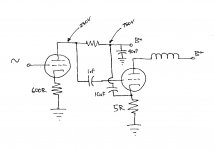
A picture of my essential setup is as below. Note that the output tube uses fixed bias.
The result? Much cleaner mid and high frequencies, including (so far as can be differentiated from high frequency lift) greater high frequency extension. The difference, to my ears, is much greater, as I said, than replacing power supply capacitors with premium varieties, and probably constitutes an upgrade equivalent to that offered by going differential, without the downside of greater complexity differential circuits entail.
Combining this method (if one does not use Ari's stacked supply method) with WE coupling should give a very quiet SE amplifier, with all the benefits of SE circuit simplicity.
A picture of my essential setup is as below. Note that the output tube uses fixed bias.
Attachments
I've thought about this a little more and have come to the conclusion that the two methods:
1) AC coupling the driver stage B+ to the output stage cathode
2) AC coupling the output stage B+ to the output stage cathode
must function in exactly the same way. The output stage cathode doesn't know the source of the noise voltage you are coupling to it.
The difference between the two methods is the noise itself. It would be interesting to run two wholly separate supplies for driver and output stage and invert the phase of the incoming AC on the driver B+ supply. Most of the noise on the two supplies (which will be residual AC hum) will then be out of phase with respect to each other and it will be easier to separate the effects of the two methods.
jeff mai said:The difference between the two methods is the noise itself. It would be interesting to run two wholly separate supplies for driver and output stage and invert the phase of the incoming AC on the driver B+ supply. Most of the noise on the two supplies (which will be residual AC hum) will then be out of phase with respect to each other and it will be easier to separate the effects of the two methods.
Driver B+ noise is amplified by the output tube---that probably is the basis for one important difference between the two methods. I take it as a defensible proposition that the earlier in an amplification chain that noise appears, the worse, as that noise is amplified by every subsequent stage. Output B+ noise, from this perspective, is the more benign.
As to most of the noise being AC hum .... my ears say otherwise in that the glaze or sheen removed from the music, as my listening experience suggests, is other than hum. Personally, I'd point to AC line noise, switching noise, capacitor and inductor dielectric noise, induced emi and rfi all as noise sources additional to hum that muck up the music. Capacitor dielectric noise, arising from dielectric absorption, is particularly annoying, IME.
serengetiplains said:As to most of the noise being AC hum .... my ears say otherwise in that the glaze or sheen removed from the music, as my listening experience suggests, is other than hum. Personally, I'd point to AC line noise, switching noise, capacitor and inductor dielectric noise, induced emi and rfi all as noise sources additional to hum that muck up the music. Capacitor dielectric noise, arising from dielectric absorption, is particularly annoying, IME.
I'd agree that the hum may not be the most objectionable part of the noise, but unless the supplies are unusually well filtered or regulated it will be the largest part of the noise. This is beside the point.
My point was that you could actually measure which noise source provides a better null on the output by using the residual AC hum on the supplies. With the driver and output stage supplies running on out of phase AC, what is actually going on would become fairly obvious when viewed on a scope. With the supplies in-phase, it would be difficult to separate the two effects.
Obviously, if B+ is shared between the two stages with no decoupling, the effect of either method is exactly the same. Even if there is decoupling, additional filtering or even wholly separate supplies, depending on the source of the noise either method of coupling could give you some or most of the effect of the other method.
Applying the two methods of coupling together might be interesting, but you'd probably have to use a scope to get it right.
jeff mai said:I'd agree that the hum may not be the most objectionable part of the noise, but unless the supplies are unusually well filtered or regulated it will be the largest part of the noise. This is beside the point.
Hi Jeff,
I think so far as your proposed experiment is concerned, the question from where the noise arises might, in fact, be the point. I personally doubt that the greater part of any noise cancelled is hum because I don't hear that noise except when music is playing. That should tell you something.
Obviously, if B+ is shared between the two stages with no decoupling, the effect of either method is exactly the same.
I think you might be overlooking an important difference. The coupling stage I'm proposing prevents, to the extent it cancels noise, the amplification of PSU noise by the output tube. WE coupling does not prevent driver B+ noise amplification by the output tube. If the output tube has a gain of 3, the coupling method I'm proposing is, roughly translated, 3X more effective at reducing noise.
Cheers,
serengetiplains said:I think so far as your proposed experiment is concerned, the question from where the noise arises might, in fact, be the point. I personally doubt that the greater part of any noise cancelled is hum because I don't hear that noise except when music is playing. That should tell you something.
It doesn't tell me anything because I can't hear it from here and even were we in the same room, we might not hear the same thing or agree on the cause of differences heard. To tell us both something a measurement is required.
My experiment was not about listening, but measuring. Even if we disagree about AC hum, it could be used as a tool to examine the relative effectiveness of power supply noise cancellation of both coupling methods.
I think you might be overlooking an important difference...
I *must* be missing something. In my mind's picture of this, if driver and output B+ are shared without decoupling then the two methods of coupling are the same because they are physically identical, i.e. the coupling cap for both is connected across the same two circuit nodes!
What am I missing?
jeff mai said:In my mind's picture of this, if driver and output B+ are shared without decoupling then the two methods of coupling are the same because they are physically identical, i.e. the coupling cap for both is connected across the same two circuit nodes!
What am I missing?
The real world of decoupled supplies? I mean, why would you be testing two circuits for any differences between them when there are no differences between them?
Cheers,
serengetiplains said:The real world of decoupled supplies?
In the real world, the supplies in a two stage amp do not have to be decoupled. Some people (in whose ears I have faith) actually prefer the sound that way. I've built amps this way, too , but have never directly compared with and without decoupling.
Also in the real world, two stages sharing the same supply are never perfectly decoupled, and are often quite poorly decoupled at very high and very low frequencies.
I'm in the real world, dude.
BTW Tom, I'm not being adversarial here. I've come around from my original position that the two methods were pretty much the same. They work in the same way (they must: a cathode isn't smart enough to know where the noise comes from), but the noise coupled is different. I believe the noise coupled in either method would always share a common component, but there would be a difference component as well. This difference component is the interesting part. Maybe one way is better than the other? Maybe they are practically identical? Maybe the two methods could be usefully combined? It would take some effort to establish this.
You're right, Jeff, and I've overlooked the value of your questioning.
Let's look at a few scenarios to see what differences might exist between the two forms of coupling. I think we agree that WE coupling is a form of feedback the goal of which is to prevent output B+ noise from appearing across the OTX primary thus preventing it from entering the transformer secondary and thus the speaker. The coupling I'm proposing is a form of feedforward the goal of which is to prevent driver B+ noise (or the B+ noise of any previous stage) from being amplified by the output tube (or next stage). From what I can see, the distinction between feedback and feedforward implies, at best, only a tiny difference in the way the two methods operate (the time-delay element).
So by method of operation---feedback/feedforward---the two forms of coupling seem virtually identical. Also identical is that both forms couple noise to the cathode.
At this point the similarities cease. WE coupling, for its part, is designed to *facilitate* a noise signal appearing at the tube anode. Feedforward is designed to *prevent* a noise signal appearing at the tube anode. Therein lies an important difference which I'll illustrate as follows.
Assume the driver and output B+ supplies are decoupled and that 50% of the driver B+ noise = output B+ noise --- this is the scenario you were posing where, in a decoupled but common supply, some noise cross-talk might be expected. Accept my 50% number for the moment.
Now assume the amp uses only WE coupling. Part of that 50% noise figure on the driver B+ will find its way to the output grid and thereby cancel part of the noise signal fed to the output cathode. Assuming the magnitude of the noise fed to the output cathode was chosen to give full B+ noise output by reference to the amplification factor of the output tube---and overlooking any adjustment required because that noise is also on the grid---the output B+ appearing on either side of the output transformer will be unmatched.
Also in this scenario, that part of the driver B+ noise that was not output B+ noise (the other 50%) will be amplified by the output tube and appear at the speaker for quality listening.
So, WE coupling only (assuming B+ crosstalk) = driver B+ noise amplified + output B+ not fully nulled.
Assume the same scenario (driver B+ noise = 50% output B+ noise), except this time with feedforward coupling only. Driver B+ noise is fed to both grid and cathode of the output the amplification of which noise is reduced due to grid-cathode nulling. What is amplified will be part output B+ and part driver B+ noise. The amplified output B+ noise will increase the amplitude of output B+ noise reproduced by the speaker.
So, feedforward coupling only (assuming B+ crosstalk) = driver B+ noise only partly amplified + output B+ noise worsened.
If we change the scenario to fully independent supplies (0% supply crosstalk), the analysis is a little easier. With WE coupling only, driver B+ noise is amplified by the output. With feedforward coupling only, output B+ noise is reproduced by the speaker.
Jeff, I do like the idea of combining the two forms of coupling. As you can see from the scenarios I drew above (assuming they're basically correct), both forms of coupling are needed for nulling driver + output B+ noise when supplies are decoupled or fully independent.
Let's also examine non-decoupled supplies in a 2-stage amp. Part of the B+ noise appearing on that supply finds its way to the grid and is accordingly amplified. If the amount of noise appearing on the grid is 50% of the supply noise, and the output tube amplifies 4X, a 2X noise signal will appear at the output anode counterphase to the noise on the B+, thus an overall 3X noise signal will appear across the output transformer to be reproduced in the speaker.
Now inject some of that noise at the cathode of the output tube. 50% noise injection would null the noise at the grid for 0X noise at the anode leaving 1X noise at B+ = 1X noise figure across OTX primary/secondary.
75% noise injection at cathode = 50% nulled by grid = 25% remaining at cathode x 4 amplification = 1X noise at anode counterphase to 1X B+ = full noise cancellation.
The above numbers are crude approximations and omit problems arising from phase shift and noise amplitude variance at the grid. Hence my conclusion "full noise cancellation" is wrong.
Regarding the varying amplitude of B+ noise transmission, if the driver is resistor loaded, say, where RL = 2Rp, an average 33% of B+ noise will appear through RL and be fed to the grid. I say "average" because the actual amount of B+ finding its way to the output grid varies according to the conduction of the driver tube, which is to say the amount of voltage drop across RL changes relative to grid voltage. Changing grid voltage causes Rp to vary which changes the voltage division in the series B+--RL--tube--ground----ie, changes the amount of B+ noise passing to the grid of the next stage. I plotted values to calculate B+ noise transmission at various points of tube operation on a 6SN7 loaded with a 68K resistor on a 750V B+ rail. To obtain the calculation, I plotted tube currents at three grid voltages and calculated the voltage drop across RL for the given current. That voltage drop, expressed as a percentage, indicates how much B+ noise appears at the stage 2 grid using the formula:
100 minus (voltage drop divided by 750) = percent of B+ noise at grid.
Here are the results:
Grid V..........Ia...............Noise Transmission (%)
0V ............. 9.7mA ................. 12
-10V .......... 7 mA ................... 36
-20V .......... 4.5mA ................. 59
In the above setup, B+ noise transmission to the output grid varies from 59 to 12 percent, the midpoint being 36%.
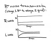
On a resistor loaded stage, the amplitude of B+ noise transmitted to the grid of the next stage therefore varies on the pattern of a tube-distorted sine wave: up and down and up and down, but not as much up as down.
One method of reducing this amplitude variance is to inductor load the driver. An inductor's high AC reactance will reduce overall variations in the voltage divider effect of B+--inductor--tube--ground where the resistive component "tube" varies. Inductive reactance, however, varies per frequency, thus the variance in B+ noise transmission will be reduced less for lower frequencies---the variance pattern, if you will, looking like ringing reducing in amplitude.
Let's also examine non-decoupled supplies in a 2-stage amp. Part of the B+ noise appearing on that supply finds its way to the grid and is accordingly amplified. If the amount of noise appearing on the grid is 50% of the supply noise, and the output tube amplifies 4X, a 2X noise signal will appear at the output anode counterphase to the noise on the B+, thus an overall 3X noise signal will appear across the output transformer to be reproduced in the speaker.
Now inject some of that noise at the cathode of the output tube. 50% noise injection would null the noise at the grid for 0X noise at the anode leaving 1X noise at B+ = 1X noise figure across OTX primary/secondary.
75% noise injection at cathode = 50% nulled by grid = 25% remaining at cathode x 4 amplification = 1X noise at anode counterphase to 1X B+ = full noise cancellation.
The above numbers are crude approximations and omit problems arising from phase shift and noise amplitude variance at the grid. Hence my conclusion "full noise cancellation" is wrong.
Regarding the varying amplitude of B+ noise transmission, if the driver is resistor loaded, say, where RL = 2Rp, an average 33% of B+ noise will appear through RL and be fed to the grid. I say "average" because the actual amount of B+ finding its way to the output grid varies according to the conduction of the driver tube, which is to say the amount of voltage drop across RL changes relative to grid voltage. Changing grid voltage causes Rp to vary which changes the voltage division in the series B+--RL--tube--ground----ie, changes the amount of B+ noise passing to the grid of the next stage. I plotted values to calculate B+ noise transmission at various points of tube operation on a 6SN7 loaded with a 68K resistor on a 750V B+ rail. To obtain the calculation, I plotted tube currents at three grid voltages and calculated the voltage drop across RL for the given current. That voltage drop, expressed as a percentage, indicates how much B+ noise appears at the stage 2 grid using the formula:
100 minus (voltage drop divided by 750) = percent of B+ noise at grid.
Here are the results:
Grid V..........Ia...............Noise Transmission (%)
0V ............. 9.7mA ................. 12
-10V .......... 7 mA ................... 36
-20V .......... 4.5mA ................. 59
In the above setup, B+ noise transmission to the output grid varies from 59 to 12 percent, the midpoint being 36%.
On a resistor loaded stage, the amplitude of B+ noise transmitted to the grid of the next stage therefore varies on the pattern of a tube-distorted sine wave: up and down and up and down, but not as much up as down.
One method of reducing this amplitude variance is to inductor load the driver. An inductor's high AC reactance will reduce overall variations in the voltage divider effect of B+--inductor--tube--ground where the resistive component "tube" varies. Inductive reactance, however, varies per frequency, thus the variance in B+ noise transmission will be reduced less for lower frequencies---the variance pattern, if you will, looking like ringing reducing in amplitude.
serengetiplains said:75% noise injection at cathode = 50% nulled by grid = 25% remaining at cathode x 4 amplification = 1X noise at anode counterphase to 1X B+ = full noise cancellation.
Whoops, I meant to say "... x 4 amplification = 1X noise at anode
in phase to 1X B+ = full noise cancellation."
- Status
- This old topic is closed. If you want to reopen this topic, contact a moderator using the "Report Post" button.
- Home
- Amplifiers
- Tubes / Valves
- Direct Coupling Modulated Bias (SET)