For the 22 and 33V diode I would suggest picking the 1Ws if available. The 33V one dissipates just under 400mW and the 22V one a little less at about 260mW.
0.5W would still handle the actual dissipation, but it will be needlessly hot... which leads to shortened lifespan of components.
Also where you have a choice, select high tolerance zeners...
A zener string of 22 and 33V could with a 5% tolerance, range from 52.25V to 57.75...
0.5W would still handle the actual dissipation, but it will be needlessly hot... which leads to shortened lifespan of components.
Also where you have a choice, select high tolerance zeners...
A zener string of 22 and 33V could with a 5% tolerance, range from 52.25V to 57.75...
Bias setting
hi, i need to know. what is the voltage for bias setup for pricission I? its using BD139 for bias....need to know bias bd139 E-B which voltage should be safe.
now my amp is opearating very nice but it's too cool.....dsn't get hot at all. all looks fine to me...
thank you.
hi, i need to know. what is the voltage for bias setup for pricission I? its using BD139 for bias....need to know bias bd139 E-B which voltage should be safe.
now my amp is opearating very nice but it's too cool.....dsn't get hot at all. all looks fine to me...
thank you.
Over 10 ohms protective resistances, the bias you will measure as DC voltage
will be 530 milivolts to the positive rail and 430 milivolts for the negative rail.
This means the current, in stand by mode, is 53 miliamperes to the positive rail nad 43 miliamperes for the negative rail.
The voltage from colector to emitter, into the VBE multiplier transistor, the bias adjustment one, will be 2.540 Volts.....also, this same BD139 will measure 673 milivolts from base to emitter.
regards,
Carlos
All transistors VBE voltages will be higher than 525 milivolts
Boys... those informations are about the Precision I.
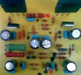
Good idea is to measure the voltage directly above (over) the power transistors emitter resistances.... if they are 0.33 ohms each one, then your voltage will be the one shown.... in milivolts of course.... but this is for 0.33 ohms emitter resistances only.
Check in all 6 transistors, to be sure all them are conducting, and they are conducting when you are able to measure some voltage over the emitter resistances...if not, they are not conducting and the bias will need some small increasing.... if measurement is high, then reduce the bias.
If you like more treble...then reduce the input condenser...you gonna have less bass... and this means to human ears, to have more treble.
Those measurement can have plus and minus 50 percent of differences compared with the values i am informing you...and this means absolutelly nothing into the amplifier operation....but..... the lower the bias, the better the treble into low volumes...but, have to check drivers and output transistors to be sure they are measuring more than 500 milivolts from base to emitter to "fine tune" the amplifier.
The picture attached is the measurement of DC voltage, without signal, with the output off set adjusted small (less than 10 milivolts), the input shorted and measurement made over the emitter resistances...means, one probe point, the red one, into the upper extreme of the resistance, into the resistance upper lead, and the other probe point, the black one, touching the lower resistance lead.
regards,
Carlos
Boys... those informations are about the Precision I.
Good idea is to measure the voltage directly above (over) the power transistors emitter resistances.... if they are 0.33 ohms each one, then your voltage will be the one shown.... in milivolts of course.... but this is for 0.33 ohms emitter resistances only.
Check in all 6 transistors, to be sure all them are conducting, and they are conducting when you are able to measure some voltage over the emitter resistances...if not, they are not conducting and the bias will need some small increasing.... if measurement is high, then reduce the bias.
If you like more treble...then reduce the input condenser...you gonna have less bass... and this means to human ears, to have more treble.
Those measurement can have plus and minus 50 percent of differences compared with the values i am informing you...and this means absolutelly nothing into the amplifier operation....but..... the lower the bias, the better the treble into low volumes...but, have to check drivers and output transistors to be sure they are measuring more than 500 milivolts from base to emitter to "fine tune" the amplifier.
The picture attached is the measurement of DC voltage, without signal, with the output off set adjusted small (less than 10 milivolts), the input shorted and measurement made over the emitter resistances...means, one probe point, the red one, into the upper extreme of the resistance, into the resistance upper lead, and the other probe point, the black one, touching the lower resistance lead.
regards,
Carlos
Attachments

I was also quite surprised by how cool the amp ran just idleing, once I had it set up as well as I could... (have some fake output transistors so they don't always behave as expected... Uncle Carlos taught me that... we actualy tried quite a few resistor values to get the right mix of VBE's... but those fake transistors only listen up to a point... I think there is one resistor vlue that will likely be optimised as you guys start building and measuring...
Measuring the emitter resistors I think you simulated that 2.5mV would be about right with "ideal" components in real life this value for me was closer to about 5mV.
Measuring the emitter resistors I think you simulated that 2.5mV would be about right with "ideal" components in real life this value for me was closer to about 5mV.
http://www.head-fi.org/forums/f6/what-strangest-part-your-bin-136832/
This guy says those caps used to be $314 each. WOW and WTF?
This guy says those caps used to be $314 each. WOW and WTF?
Maybe they will give you a very metalic sound
Well.... they are "metalized"... and the long shape may produce long bass...heheheh
I used to replace them, almost the same capacitors, into the sixties.... i used to dismount to observe inside...metalized coiled material
I remember this one, metalized this same way, the same brand, Sprague, beeing used in an enormous wooden furniture i had.... an old Brazilian Made Telefunken, tube amplifier assembled into a furniture, with 6 speakers, a Polivox turntable, a Short Wave band receiver and excelent 12 watts each channel power.
Those early days i used to remove and substitute, i had not knowledge and i had the imagination those things waste alike a battery, you see, people told me capacitors discharge!.....hehehe
Well, in the past people have not discovered "Unobtanium" and all those foolishes....now a days, those crazy guys that will spend enormous money in such things really deserve to be fooled because their non sense beliefs.
One day people will sell sheet as High Technology Carbon material as magic compound to grown plants.... 100 dollares a piece of.....
Of course i do not believe in such foolishes, i am just beeing ironic and kidding.
regards,
Carlos

I am very happy that i was "nominated", indicated, included, by
Brazilian Orkut folks (36 Millions of users of Orkut in Brasil) as the Master of Electrons into audio amplifiers.
Even knowing they are kidding with me, i felt myself very proud because i could make a lot of friends in my country too.
They have included me into the list of important folks as:
Joule
Gauss
Coulomb
Einstein
Planck
Volta
Ohm
Watt
Hertz
Ampere
And finally Carlos Mergulhão... with the expertise to manipulate spinning electrons.
ahahahaha.... good mood those folks.
Carlos
Attachments


I visited the SBE capacitor factory in Vermont a few years ago and got a tour of how they build capacitors. They make the orange drops that Sprague sells as Sprague caps. They are really SBE caps. They have been making them since before WWII. They told me the process has changed zero percent. They still use exact same technology and same machines. No change at all. They recently came out with a new cap though that discharges very fast with a huge amount of uF. They call it their pulse capacitor and it is used in stun guns and things like rail guns. Basically they have a metal foil and a sheet of plastic and a plastic bobbin. The plastic bobbin spins rapidly and winds the sheet of plastic with the metal foil inbetween the coils of plastic. When all is wound they place a wire across the side of the coil and spray molten aluminum at the side of the coil which basically solders the wire and coils of metal foil together on that side. I forget how the opposite side is attached. I dont remember if its the same process, or if it is soldered to the first inch or so of foil, or the last inch or so of foil. Not sure. Then whole thing is dipped in the molten orange. Each one is tested by machine. Most of their capacitors are self healing. So if one gets a burn, which is basically a hole in the foil from when a spark from one turn of foil to arcs to the other turn of foil, then oxidation repairs the hole. By the way, SBE rates all of its caps at one half the real rated voltage. So if you get one that says 100VDC it will really handle 200VDC. That was told to me by their head salesman Stuart Delduca and by their head engineer. (I think they only have one engineer) Its actually a very small factory. Maybe 10,000 square feet.
Uriah
Uriah
I was discussing that with dear nephew Nordic some monthes ago
I told him, because my age, that i have found that...the condensers have a guaranteed voltage very lower related their real possibilities to hold bigger voltage.... i have suspections that he was not entirelly convinced about that.
Good that you wrote this information here... this is good for people that is using 35 volts supplies, and this allow those folks to buy cheaper condensers than the 70 volts units they use to buy.
As condensers, can hold much more voltage then the informations written into the plastic cover...when you find someone that has written 35 volts on it, will be absolutelly no problem to use it with 35 volts, even considering the mains voltage fluctuations..... even thinking about rail to rail voltage and even thinking into rail to rail voltage swing.
regards,
Carlos
I should point out that Stuart was VERY proud of the fact he could offer caps that could handle double the rated voltage. I know this is possible with genuine SBE caps, however I dont know about other brands and I dont know if this applies to Aluminum Electrolytics.
Carlos, do you think Aluminum Electrolytics are spec'd 50% lower than they can handle or do you think maybe a little less?
Uriah
Carlos, do you think Aluminum Electrolytics are spec'd 50% lower than they can handle or do you think maybe a little less?
Uriah
I think, and have tried several times, that can hold 50 percent more voltage
And i had not exploded units....normally, daily, i am using 25 percent more voltage to 35 Volts condenser in one of my amplifiers.... because the supply is weak and i use to loose that extra voltage during the peaks...but almost all the time they are receiving 25 percent more volts than the 35 volts written into the plastic cover.
I do not suggest people to do that, because some can hold and maybe you gonna find one or two brands that will leak or explode....but.... try to think alike the factory.... alike the manufacturer...how can he adjust this to be exactly that voltage...of course will be higher...and off course they will put higher and higher because of safety reasons.
I think ALL them do this way..... why i think this way...because i do not think they are idiots to accept ANY kind of risk into their production.
Also you have a "difference" to sell..... your @$#%@ capacitors brand can hold twice the power.... this is very impressive, as you will be giving twice the voltage by the same price..... this is economy, reliability and good Marketing idea to advertising from mouth to mouth during sales activities.
-"DX amplifiers are the only ones have THD and IMD, but certainly you will not perceive...not perceiving will not bother you"
Observe how many constructed..... the differential offered....i could told them 0.1 % of distortion, as depending the power i can have 0.001 % of distortion...it is a matter to select a number to publish....but "will not ashame you"..... " cheaper than others"..... "easy to make".... and "distortions not bothering".... "the only one that has beautifull noises when you turn power off"....those things are differentials to sales.
regards,
Carlos
I have four valve monoblocks where some of the high voltage Power Supply electrolytics are rated only a little higher than the supply voltage. Several of the caps broke down, making a mess inside the amps. The reason the inadequately rated caps were used was that suitable higher rated ones were noy available.
I now use a Variac so that I can run the supply voltage a little lower, and hopefully inprove reliability.
Personally I prefer to use electrolytic capacitors rated at 15 to 20% higher than the supply voltage.
billabong.
I now use a Variac so that I can run the supply voltage a little lower, and hopefully inprove reliability.
Personally I prefer to use electrolytic capacitors rated at 15 to 20% higher than the supply voltage.
billabong.
Fully agreement Bilabong.... high voltage is something dangerous
My rules and knowledge do not apply to tubes and high voltage...i have no experience about.
I suppose the insulation is more critical into those voltages, as eletrons are hardly atracted to jump from pole to pole and open holes into insulating material.
My experience was from 50 volts and down voltage related fifty volts....cannot say nothing above that as i have not tested...maximum was 50 volts condenser operating in 77 volts without burn...still working here...have fuses to avoid to explode if i have a short inside.
I am here in solid state, because this is the small knowledge i could learn, as i have studied amplifiers, solid state, all my life...but tubes, i have made once...found them hot and i give up.
regards,
Carlos
- Status
- Not open for further replies.
- Home
- Amplifiers
- Solid State
- Destroyer x Amplifier...Dx amp...my amplifier