Boys...you really can construct Dx amplifier...it is really nice
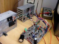
This is one more ... another poor amplifier "smashed" by Dx amplifier.
I cannot tell you the amplifier name...the guy is from our forum.
Not his best design, the guy has other.
The list of smashed ones is turning long.
regards,
Carlos
This is one more ... another poor amplifier "smashed" by Dx amplifier.
I cannot tell you the amplifier name...the guy is from our forum.
Not his best design, the guy has other.
The list of smashed ones is turning long.
regards,
Carlos
Attachments
Hi Gaetan,
There are going to be pros and cons here, because a rule cannot be set.
Transistor action is optimum without an emitter resistor.
When an amplifier has many stages with much gain to spare for NFB, then emitter resistors will relate more to a fractional loss of output swing than to loss of output stage gain.
Emitter resistors will degrade the performance of Carlos' amp.
Additional gain by using an input mirror within the DX would cover any emitter resistor gain loss, but then the mirror would affect the performance too, so no point !
However when devices are used in parallel, then the combined internal emitter resistances of two devices in series with a current sharing resistor of say 0.47R each, more or less brings average performance back to one device without emitter resistor.
Hi Nordic,
The higher value capacitors maintain the timing of that acoustic bass coupling, and stop kick drums from sounding floppy. The DX will also give an excellent sense of snap timing for rim strikes.
Subwoofer. Yes these can provide palpable experience of drums and ambience, but so very often the sound 'goes wrong' because kicks and bass guitar just become a jumbled mess, thus no longer being music that is easy to listen to. A little clarity is better than a load of show-off thump-thud, for you don't tire of that which does not distract your mind. This being a reason so many designers deliberately choose to fit smaller value input capacitors, because our brains can still 'hear' bass notes which are not reproduced at full power, and when the LSs are not trying and failing to reproduce them, everything else comes through much more cleanly.
Timing is the key. Both with NFB (DX '") '), and a driven LS system.
'), and a driven LS system.
Cheers ......... Graham.
There are going to be pros and cons here, because a rule cannot be set.
Transistor action is optimum without an emitter resistor.
When an amplifier has many stages with much gain to spare for NFB, then emitter resistors will relate more to a fractional loss of output swing than to loss of output stage gain.
Emitter resistors will degrade the performance of Carlos' amp.
Additional gain by using an input mirror within the DX would cover any emitter resistor gain loss, but then the mirror would affect the performance too, so no point !
However when devices are used in parallel, then the combined internal emitter resistances of two devices in series with a current sharing resistor of say 0.47R each, more or less brings average performance back to one device without emitter resistor.
Hi Nordic,
The higher value capacitors maintain the timing of that acoustic bass coupling, and stop kick drums from sounding floppy. The DX will also give an excellent sense of snap timing for rim strikes.
Subwoofer. Yes these can provide palpable experience of drums and ambience, but so very often the sound 'goes wrong' because kicks and bass guitar just become a jumbled mess, thus no longer being music that is easy to listen to. A little clarity is better than a load of show-off thump-thud, for you don't tire of that which does not distract your mind. This being a reason so many designers deliberately choose to fit smaller value input capacitors, because our brains can still 'hear' bass notes which are not reproduced at full power, and when the LSs are not trying and failing to reproduce them, everything else comes through much more cleanly.
Timing is the key. Both with NFB (DX '
'), and a driven LS system.Cheers ......... Graham.
Normally this is produced by bad solder joint.
Solder must be shining, a shine polished surface....cannot breath over the solder to force it to cool down...never do that.
Also, do not melt solder into the soldering iron to then transfer the melted solder to the component lead...this will produce problems.
The component parts must be cleaned in advance to solder.... a small knife will needed to clean oxide out from the component leads.
Clean your soldering hot tip when soldering.. from time to time scratch the tip into a wet cloth, to remove burned parts, carbon and used flux (do not use sandpapper or stell brush to do that)... cloth and water is the best idea.
Use solder that already has flux inside the wire.... avoid external flux as it can be contaminated or had dirty inside, or oxide, or small particles of solder (small bubbles, small balls of solder)
Remove all cleaning products you have used in advance of soldering.
Do not use (never) varnish or other product over or under the board..some of them are conductive.
Motor boating is a very old noise produced by the need of electrolitic condensers, or capacitors, depending the current, to be installed after resistances..... a rail resistance, for example, without a condenser int he left side will produce noises and unstabilities.
Some noises can be produced shacking the board...touching it, or hitting it with a pencil (wood, insulating material...never screw driver)... others will need to touch the soldering iron tip into the damaged solder place....if boil...or pops during soldering, this seems you have problems there.....gazes cannot flow out from the solder when soldering... contamination is the cause when you have this boiling and popping effect.
Parts subjected to strong mechanical stress can broke...this happens with some resistances that brokes into extremes... seems fine, but the electrical contact is loosen....not tigth, not "soldered" and this produces noises...also defective capacitors or condenser produces this....i had one transistor in 1969 that produced noises...was "microphonic"...but was down the sixties...now a days i think this will not happens anymore.
Normally noises are consequence of human effect.... errors...construction errors....non good electrical contact.
regards,
Carlos
why?cannot breath over the solder to force it to cool down.
Never heard that before. Maybe I don't read/listen enough.
Have to admit I'm a blower too Andrew...
will need to check those track repairs....
But I will follow up on al the advice....
Sound stays normal...
Only crackle and pops... pretty mutch from startup now...
regardless of source volume...
And here I was haveing fun playing subwoofer repairman until 2 in the morning, with my new skills... (PS... I'm dead tired, and my watch lost 2 hours overnight...) Still haven't found the problem though... the idiot ex-owner... connected it to, wait for it.... a car battery...
All transistors tested so far, look ok, but there are also 2 transformers and some stupid inline dual opamp... and even an inline 555 timer... will have to make little adapter boards, if it is one of those, broken...
Hi Graham, no, it is two diffirent things... IC's are in the subwoofer I'm working on...
I opened the DX's lid, the crackleing channel is the one we got working first.. the one that "fixed itself" so very likely a solder problem... I was a bit surprised that there would be solder issues with the last channel we got to work... fixes look mean, but I feel they were solidly made...still have some hum from that channel... but will check biasing and everything... at least we know it can play.
I opened the DX's lid, the crackleing channel is the one we got working first.. the one that "fixed itself" so very likely a solder problem... I was a bit surprised that there would be solder issues with the last channel we got to work... fixes look mean, but I feel they were solidly made...still have some hum from that channel... but will check biasing and everything... at least we know it can play.
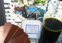
Nordic, I'm happy for you with the progress you've made, but a little sad you still have a problem.
microp, impressive picture of your dead speaker . How is the turbo coming along ?
With luck I'll have six channels by the end of the day So exciting. Two areas of question if anyone has the time.
1) Protection.
I know the recommended fuse plus wire trick, how does this compare against using relays for protection ?
If I understand correctly, the problem with using a series relay on the output is finding a relay that will reliably switch the voltage and current that may be found under DC output failure.
Given the quite small capacitance in the recommended psu, would it be sufficient to use a relay to disconnect the AC at either the primary or secondary ? I ask because I will probably have relays in the primary to enable remote switch on / switch off.
2) psu Inductors.
I'm a total inductor virgin and while I have done some research on the net I've not found enough information to boost my confidence over winding the things.
The wire I have is 1.25mm, the 20 + 20 turn coil will be slightly longer than than the 3r3 resistors. Is this a problem ?
Should I use a loop of thread or such to keep the turns close together.
Does it matter that the diameter of the coil is slightly larger than the diameter of the resistor ?
<chuckle> The 'to do' list is down to mount op transistors, build psu, some case work. Not sure which to do next. All exciting knowing how close each would take me to the final goal. Think I'll procrastinate for a while, lol, and think if I've missed something.
microp, impressive picture of your dead speaker
. How is the turbo coming along ?With luck I'll have six channels by the end of the day
So exciting. Two areas of question if anyone has the time.1) Protection.
I know the recommended fuse plus wire trick, how does this compare against using relays for protection ?
If I understand correctly, the problem with using a series relay on the output is finding a relay that will reliably switch the voltage and current that may be found under DC output failure.
Given the quite small capacitance in the recommended psu, would it be sufficient to use a relay to disconnect the AC at either the primary or secondary ? I ask because I will probably have relays in the primary to enable remote switch on / switch off.
2) psu Inductors.
I'm a total inductor virgin and while I have done some research on the net I've not found enough information to boost my confidence over winding the things.
The wire I have is 1.25mm, the 20 + 20 turn coil will be slightly longer than than the 3r3 resistors. Is this a problem ?
Should I use a loop of thread or such to keep the turns close together.
Does it matter that the diameter of the coil is slightly larger than the diameter of the resistor ?
<chuckle> The 'to do' list is down to mount op transistors, build psu, some case work. Not sure which to do next. All exciting knowing how close each would take me to the final goal. Think I'll procrastinate for a while, lol, and think if I've missed something.
Hi Nordic,
Wobble each component - only one at a time.
The act of blowing makes you shake if you are holding something, or the solder appear grainy instead of smooth.
(Look at all Carlos' different prototypes - no dry joints there.)
Nordic - an iron which is too hot will not 'solder' properly either because of cooling (graining) stresses within the joint.
If you find a suspect joint - you don't just reheat with fresh solder, but you need to remove solder and check that the surfaces have not become oxidised. Scrape wire and track with a craft knife blade, re-tin and then re-solder.
Cheers ......... Graham.
Good solder is an important know how... i have a good teacher.
There are steps to follow:
1- clean the component lead, remove oxide or glue from the adhesive tape tha is used to keep components together.
2- cleaning can be done by erosion, using a small knife...remove the oxide.
3 - Touch the component lead into the soldering iron tip, and them touch the solder into the junction you have, soldering iron and component lead...solder will melt...move component lead up and down to produce a layer over the component lead..... wait each lead cool down to go the the next. (transistor may burn if you apply heat to the three leads, more than 3 seconds each one!).
4 - Clean soldering iron tip each step...for each lead one cleaning into soldering iron tip...cloth dampened with watter will be the best option. The cloth is not wet...it is humid only.
5 - If needed, clean the transistor, or component leads once more, using a small knife but tender touch...just to remove excesses of flux and surface discontinuities.... to match the board's holes for instance.
6 - When soldering into a copper board, a circuit board, clean the board in advance, a thin and soft steel brush and be used, those steel foams used into kitchen to polish aluminium can pots or sandpapper grain 400 (very thin)...this is to remove coating and oxide from surface.
7 - When soldering, triple contact will be needed... component lead must be in contact with the soldering iron point and the solder will produce the contact (electrical and thermical) from the component lead together soldering iron tip with the board's cooper... do not move soldering iron... wait a second while solder melt and goes increasing the melt material circle...then remove soldering iron and never breath over..wait it cool down naturally.
- " do not move soldering iron tip.... it is not to be moved...keep it there and wait heat transference"
Clean the board using Alcohol, Methylated Spirits as Graham said, Aviation fuel called Kerozene here in my country will work too.
Acetone, benzine and others can dilute condenser silk screen indications, acetone can melt some plastic too, transistor will loose bright and the indications will disappear
Solder surface must shine, without bubbles.... cannot loose brigthness!
regards,
Carlos
Attachments
I am still searching for "one step up" amplifiers
Something that reproduces with better (clear better, immediatelly perceived into A to B comparison, without any doubts) better amplifiers than Dx amplifier related sonics...not circuit complications, will increase of distortions and costs as i am perceiving in my home...testing!....or those said non distortion that sounds awfull (there are many...you do not imagine how many they are!)
I know Dx amplifier technologie is old, that exist better circuits, more stable units, faster circuits...but i am searching for sonics....better sonics...clear better sonics...not that one has only better bass and awfull voices...or other with extremelly good treble and terrible voices and bass....other with excelent dinamics, but mufled, awfully mufled!...i want something that can beat Dx in all battle fronts...better bass, better treble, better dinamic, better voices, better sound stage, and using 37 volts.
I am still searching...i can imagine more than 4300 units already constructed.... recently, i have made 16 modern amplifiers, and no one could EVEN sound so good as.
Now, i have more product to etch boards, more boards, i have bougth more 1 meter size board plates, and also more solder, more transistors, and i am ready to produce 2 units each day to test and compare.
No designer had courage!....yes...they had not courage, to offer me top performer designs.....only Hugh...but this i already know that can win Dx amplifier.... i want DIY schematics....non professional amplifiers, to home made, without ICs that was made with Jupiter Sand or connectors with Isobarium of Nothing or capacitors using Selenium dopped with rich Uranium, unobtanium, inexistium or something alike....i want sonics!
In less than one ear...i will check ALL forum amplifiers!
I am searching amplifiers using BGTs, without FETs, without Chips...using discrete transistors and resistances and capacitors, and diodes, also trimpots, Leds, zener...not problem....able to work using 37 plus and 37 negative that can sound superior to simple Dx amplifier.... not measurements superiority...sound superiority!..something children can perceive as better, old guys, audiophiles and non audiophiles can fast perceive too.... things tested, compared A to B.... when everyone will perceive the one is really better!
I told that simple bootstrapped amplifiers will not be ashamed by anyone, that can lose, but the margin, the distance, the number of points into classification would be small....now i want to prove you that, and i am ready to construct ALL forum amplifiers...they can be 1000, 2000 or 3000 units...i will check them all!
And will tell you...CLEARLY, the ones could beat Dx amplifier.
People that have not offered me their designs, but had published....can start to shake their bonds, and keep themselves hidden under the bed.... with afraid of crazy DX..... relax, i will know how your amplifier will sound...but i will not smash it in this forum.... i will show the circuit, people will not have conditions to identify your schematic there...YOU will!
hehe....Dx is turning very, very bad...hehe... if you wanna know..those snobish folks that do not show diagrams...i have already discovered analising images and some of them were already smashed by Dx amplifier.... i have made 3 amplifiers from those ones use chip amplifiers, operational amplifiers and field effect transistors.
But those ones are scared..... i want more courageous people to have the chance to beat Dx amplifier, and to read that this happened and published..other ones can keep their selfish complications, and continue to delirate about invisible, non audible qualities, or pretty waveforms.
No....you are wrong...i do not think i am special....and that my amplifier is glorious unique wonderfull thing in the earth...it is not...it is not even wonderfull, it is only good enougth.
I am telling you, that amplifiers just amplify energy, tracking the input signal, they have the obligation to increase power (voltage multiplied by current) and ALL them sounds almost the same...differences are small...complications are enormous...lyes are incredible big too...and delirium is impossible to measure...hot parts,. hot cables, hot panels...all this...all this..... this is a ....
regards,
Carlos
Attachments
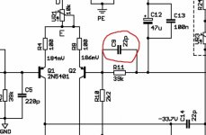
Is this a Dx clone?
You decide.
- "Dx is that amplifier that had the schematic copied by a pre-existent industry...now a days, the schematic is almost a Dx copy"
The industry exists since 2002 (or older than that) and i ensure you that i have made the calculations that resulted into Dx resistances values... and all decisions about Dx amplifier...how this can happen without copy..... Telepathic.... magic?
Maybe someone dead into this company travelled with spirit to my body and made me design this way...ahahahaha.
It was a very small imagination....just selecting other currents the resistances values would be really different..also other supply voltage.... small imagination or the most terrible coincidence!
regards,
Carlos
Attachments
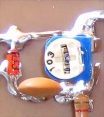
I do not know dear Gaetan....this is adjusted during construction
We know, listening, the bigger the capacitor is, the worst is the treble.
Also we know, the smaller it is, more easy to the amplifier to oscilate.
I decided to a safe value....not small, not too big.
Latter, Graham Maynard said that i could peak it to the best possible performance.
The method is to inject audio signal into the amplifier, not exactly audio, but FM inter station hiss.
Than you have a substitute capacitor to that position, a radio frequency variable capacitor.... listening the hissing sound into the speaker you go increasing the capacitance (going to close the air gap variable capacitor) till you have the sound peaked... then advance a little bit.
Removing the variable capacitor, and measuring it with a capacimeter, you will know the optimised value to your circuit.
With small increasings, the capacitor result remains not so different into sonics....but decreasing affect the sound a lot!
Do you really need that answer in frequency?... i will have to check it into the simulator to tell you the frequency.... for sure the frequency were it starts is higher than you can listen.... so...it cleans, because of feedback, those frequencies that turns the audio spectrum "dirty" of waste frequencies.
The 27 picofarads is already working around 80 kilohertz.... into 150 kilohertz it already have attenuated spurious signals to 50 percent of amplitude
regards,
Carlos
- Status
- Not open for further replies.
- Home
- Amplifiers
- Solid State
- Destroyer x Amplifier...Dx amp...my amplifier