hi, esltransformerI cleaned my basement and i found some interstage transformers.
Is for a small tube Ri 6k-8kOhm, 10mA, 8-140kHz frequency response (at 7,7kOhm)
It has a HIB c-core.
Anybody interested? Just €100,- each.
I have a bigger one too, for Ecc99/6H30. 7-420kHz at 2300Ohm,25mA.
Your interstage bifilar, I have a question:
1. what method winding - "randomly", "turn to turn," "universal" (see photo
An externally hosted image should be here but it was not working when we last tested it.
), "and return", or some other method? for reducing capacitance...2. What area of the core, in square cm. ?
3. What inductance? to 5mA, 10mA, 20mA ... ? did you do the measurement ?
4. it can be used for 6S45P-E, 40 mA? What inductance? What frequency response (at 1,2 kOhm) ?
thanks.
Not esltransformer, but universal is for RF chokes and transformers. It's advantage is very low interwinding capacitance.
It is not useful for AF interstage transformers.
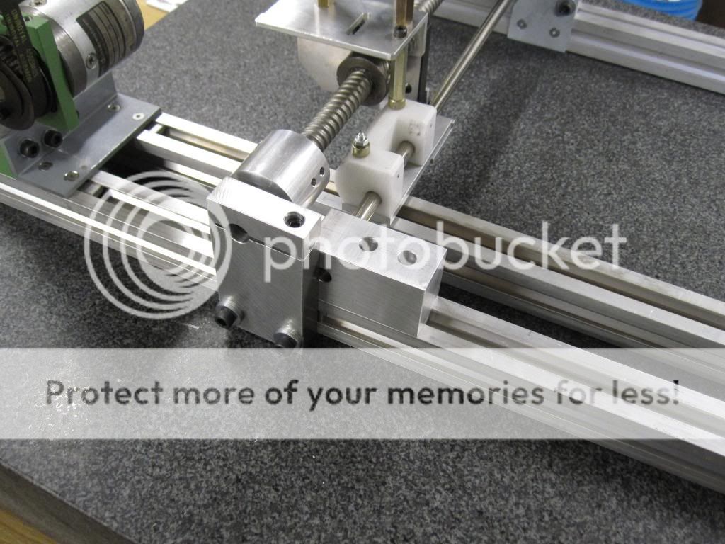
I have not built my transformers yet as I am building a coil winding machine first.
I plan on straight bifilar stack wound with EI-100 cores using a 1" stack (6.45 sq-cm). The prototype transformers will be on EI-85 cores with .85" stack (3.36 sq-cm). I will probably try two different winding techniques to compare, as I have two sets of EI-85 cores.
It is not useful for AF interstage transformers.
I have not built my transformers yet as I am building a coil winding machine first.
I plan on straight bifilar stack wound with EI-100 cores using a 1" stack (6.45 sq-cm). The prototype transformers will be on EI-85 cores with .85" stack (3.36 sq-cm). I will probably try two different winding techniques to compare, as I have two sets of EI-85 cores.
hi, esltransformer
Your interstage bifilar, I have a question:
1. what method winding - "randomly", "turn to turn," "universal" (see photoAn externally hosted image should be here but it was not working when we last tested it.), "and return", or some other method? for reducing capacitance...
2. What area of the core, in square cm. ?
3. What inductance? to 5mA, 10mA, 20mA ... ? did you do the measurement ?
4. it can be used for 6S45P-E, 40 mA? What inductance? What frequency response (at 1,2 kOhm) ?
thanks.
If you want a interstage for a 6s45 i can make a custom transformer for you.
It wil be nicely wound in layers. Low frequency response depends on your wishes.
If you are not in a hurry, in summer i will be in Ukraine so shipment can be cheaper for you.
This is very interesting! When you will be in Ukraine - let me know!If you want a interstage for a 6s45 i can make a custom transformer for you.
It wil be nicely wound in layers. Low frequency response depends on your wishes.
If you are not in a hurry, in summer i will be in Ukraine so shipment can be cheaper for you.
thanks
This is very interesting! When you will be in Ukraine - let me know!
thanks
You have a pm.
Btw, i like to use a large c-core so the copper losses will be lower then small cores. The core losses can be lower too if proper designed.
An externally hosted image should be here but it was not working when we last tested it.
An externally hosted image should be here but it was not working when we last tested it.
An externally hosted image should be here but it was not working when we last tested it.
Looks nice.
I'm working on a program to control mine using an Arduino MEGA2560 with a 4X20 display and 5 key pad ( up, dn, lt, rt, enter).
I was hoping not to re-invent the wheel, but have been unable to find source code other than ArdWinder. The ArdWinder code that is available does not seem to be complete, and looks like it hasn't been worked on in a year or more.
Last edited:
Hi,
The control/software part is still very much an open question, I hope some of my friends can help me with that part since I know next to nothing about programming. On the other hand, one week ago I knew nothing about stepper motors either so I guess everything can be learned.
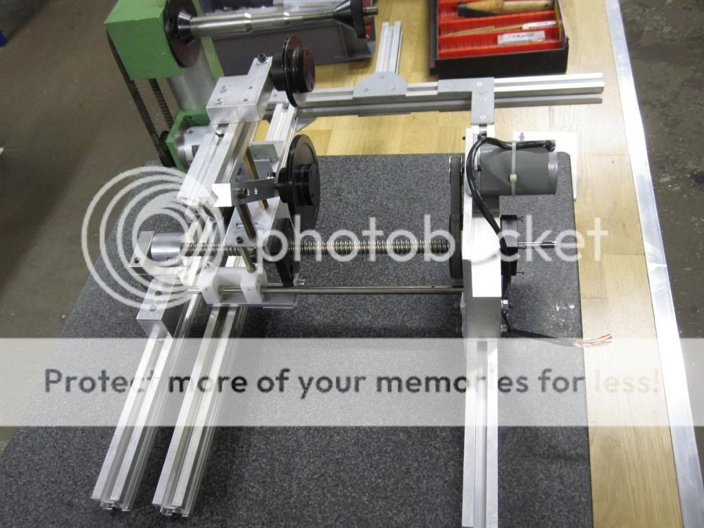
Still need to find or buy a large stepper motor for the spindle and driver boards for both spindle and traverse before I can get things moving.
Right now I´m working on a servo controlled wire tension system, definitely not the easiest thing to do and I´m trying too keep my ambitions on a somewhat realistic level.
The control/software part is still very much an open question, I hope some of my friends can help me with that part since I know next to nothing about programming. On the other hand, one week ago I knew nothing about stepper motors either so I guess everything can be learned.
Still need to find or buy a large stepper motor for the spindle and driver boards for both spindle and traverse before I can get things moving.
Right now I´m working on a servo controlled wire tension system, definitely not the easiest thing to do and I´m trying too keep my ambitions on a somewhat realistic level.

I'll use a spring loaded wire tensioner with friction drag for the first pass.
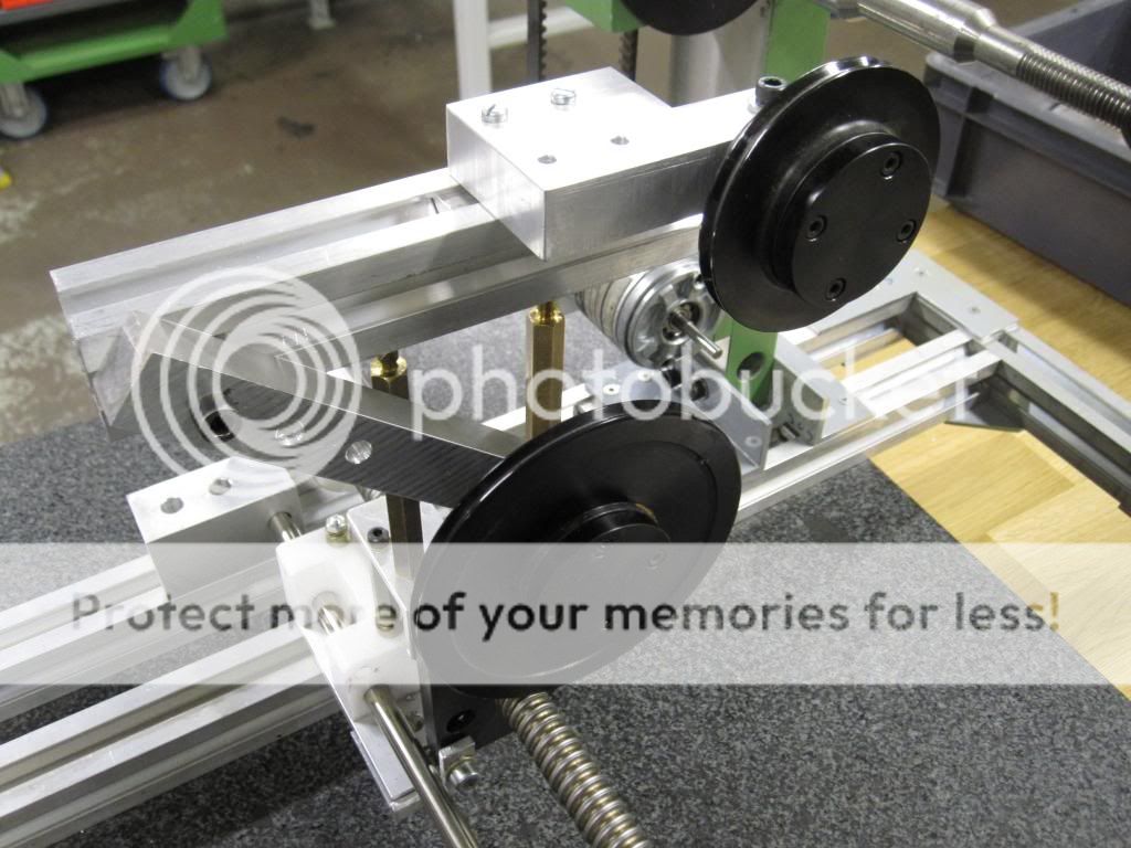
I'm using a NEMA17 motor for the traverse mechanism and a NEMA23 for the spindle. I had hoped to use a NEMA34 (overkill) that I salvaged about 20 years ago, but it is toast.
The NEMA23 should have plenty of torque based on the tests I've done so far with the NEMA17.
I have limited programming experience, but think I can muddle through.
The NEMA17 starts having problems at 300steps per second (200step/rev) and I think it may limit my winding speed. I'm concerned about running too fast and losing sync, so I may need to use an interrupt routine with a opt interrupter to keep track of rotation. One possibility is to use two sensors with slight phase offset to insure I can track direction.
I've been looking at interrupt operation of the Arduino today.
First indications are that I can run three motors simultaneously,but I have to be very careful to keep the main routine lean or everything slows down.
Hi TheGimp, have you tried microstepping your motor? Quite often if you drive one directly using a square wave it will resonate at some frequency and drop out of sync.
Here's a link:
Stepperworld Microstepping Tutorial
Cheers Matt.
Here's a link:
Stepperworld Microstepping Tutorial
Cheers Matt.
Thanks Matt, I'll read that. I had read of microstepping before but never read the theory behind it.
Fuling, I hadn't messed with steppers till a couple of months ago. I started by pulling the head position stepper out of a 5-1/4" floppy drive and driving it with a ULN2002 transistor array. Easy to work with and it is very insightful to actually make one work.
Like most endeavors, it is confusing at first, but if you persist it will make sense. Thankfully, there is a lot of good information here and on the internet in general. There are lots of good sites like the one Matt pointed out.

Two Steppers Running
I got the code far enough to test the synchronization of the motors. I think the acceleration factors will need tweaking to get it right, but it is close for a first pass (5.8% error is not near good enough).
Feature creep has taken over the project and it looks like I will try to implement multi-section capability before I integrate the controller and hardware.
Good news on the NEMA23 motor, it should be plenty powerful enough. Even running at .5A/winding (resistive current limiting) I can't hold the shaft and stop it from turning. I estimate it should operate around 2A based on the physical size, resistance and inductance measurements. So it should have plenty of torque without using reduction pulleys (which would slow it down).
I plan on using a comparator to measure the voltage drop across a sense resistor to limit the current rather than using resistive drop, but the initial test of the comparator feedback looked wrong so I set it aside for now.
I'll get back to it once I have the code ready.
Attachments

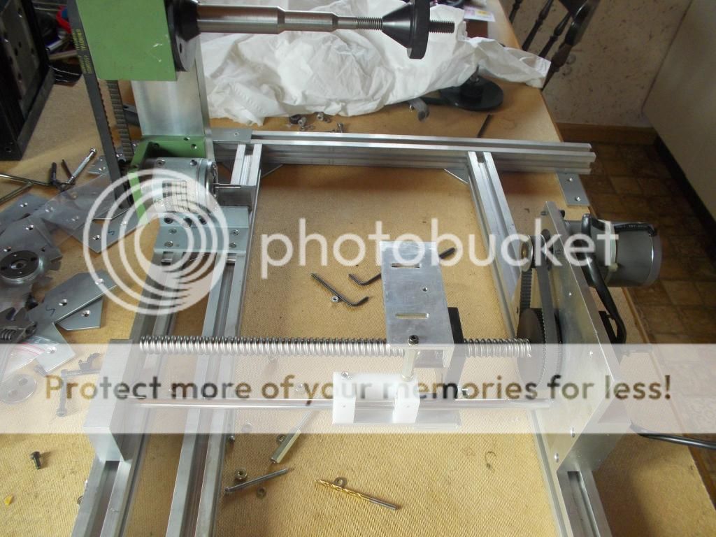
Progress is slow as I keep thinking of additional features/functions that should be in the F/W, like adding a limit switch for home position of the traverse drive so it is easier to send it back to a known position.
I'm interleaving working on F/W and working on the mechanism.
Latest on the chassis is that the basic panels and angle brackets for assembly are cut and fitted.
I'm interleaving working on F/W and working on the mechanism.
Latest on the chassis is that the basic panels and angle brackets for assembly are cut and fitted.
Attachments
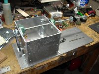
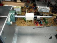
How large does the spindle and clamp need to be? This is what I'm currently thinking of, with a bobbin for an EI85 core in place.
Currently I plan on setting up for a max of EI-150, which looks like it is much larger than anything I anticipate winding.
Beyond the length of the spindle clamp rod, the size of the core effects the distance from the wire feed mechanism to minimize changes in wire feed geometry.
Any thoughts?
Currently I plan on setting up for a max of EI-150, which looks like it is much larger than anything I anticipate winding.
Beyond the length of the spindle clamp rod, the size of the core effects the distance from the wire feed mechanism to minimize changes in wire feed geometry.
Any thoughts?
Attachments
- Status
- This old topic is closed. If you want to reopen this topic, contact a moderator using the "Report Post" button.
- Home
- Amplifiers
- Tubes / Valves
- Designing an Interstage Transformer