I wonder why winding it neatly when a more messy backandforth winding is more effective and gives higher inductance

Of course: you waste window space (which is always lacking), winding has longer wire length for the same amount of turns, and it does *NOT* have more inductance, which depends on nº of turns only.but other than looking messy, I guess the backandforth wound will have other drawbacks ?
the reason I posted about it is that I just rewound a small crosover toroid
it was 'scatter wound', as usually used with toroids
I carefully rewound it using the same wire
looked quite neat, but ended up with only 2mH, instead of the 4mH it had before
but maybe I made some silly unknown mistake
but I understand the capacitance is the real problem
it was 'scatter wound', as usually used with toroids
I carefully rewound it using the same wire
looked quite neat, but ended up with only 2mH, instead of the 4mH it had before
but maybe I made some silly unknown mistake
but I understand the capacitance is the real problem
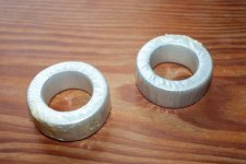
may looks just a bit different, but not that much
its wound with two wires in one go
making two paralel windings with each 0.5mH
connected in series they give 2mH
that considered, maybe it really wouldnt really take much more copper to make it 4mH
well...I may have snapped off the small bit of wire that made the original scatter wound
its wound with two wires in one go
making two paralel windings with each 0.5mH
connected in series they give 2mH
that considered, maybe it really wouldnt really take much more copper to make it 4mH
well...I may have snapped off the small bit of wire that made the original scatter wound
Attachments
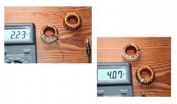
born curious, so I pulled off all wire from both cores
2.2mH had 5.0 meter wire
4mH had 6.5 meter
math is not my strong side
but basicly it means 30% more wire put in more or less randomly doubles the inductance
now, my question is ????.... will it matter where the exstra 30% wire is placed...last ?..or first ?
if I understand mr Fahey correctly, it wouldnt make any difference
...... inductance, which depends on nº of turns only.
Attachments
born curious, so I pulled off all wire from both cores
2.2mH had 5.0 meter wire
4mH had 6.5 meter
math is not my strong side
but basicly it means 30% more wire put in more or less randomly doubles the inductance
now, my question is ????.... will it matter where the exstra 30% wire is placed...last ?..or first ?
if I understand mr Fahey correctly, it wouldnt make any difference
L = 4 π μ S N^2 / (9 l x 10^8)
Maybe this answer your question, L depends on N^2, not N.
...
but basicly it means 30% more wire put in more or less randomly doubles the inductance
now, my question is ????.... will it matter where the exstra 30% wire is placed...last ?..or first ?
if I understand mr Fahey correctly, it wouldnt make any difference
Close, to double the inductance you need the square root of 2 (1.41 or 41%) more turns.
Only the number of passes through the core matter (leakage inductance and capacitance depend on the winding technique).
Thanks
-Antonio
ah, I see, thanks
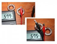
I now decided to forget about close nice looking winding, but instead focus solely on tightness
first 'layer' is now actually two 'rounds' of winding
but no doubt a toroid is different
a tighter winding raised the bar from about 0.50mH to 0.57mH
doesnt look like much, but is still 14% higher
but only need to squeeze it with two fingers to get it to 0.6mH,
so I expect the first winding will increase further once the second winding comes on
hey, I know its not advanced interstage, but now tempted to try a signal splitter for my bass guitar preamp
Attachments
I cleaned my basement and i found some interstage transformers.
Is for a small tube Ri 6k-8kOhm, 10mA, 8-140kHz frequency response (at 7,7kOhm)
It has a HIB c-core.
Anybody interested? Just €100,- each.
I have a bigger one too, for Ecc99/6H30. 7-420kHz at 2300Ohm,25mA.
Is for a small tube Ri 6k-8kOhm, 10mA, 8-140kHz frequency response (at 7,7kOhm)
It has a HIB c-core.
Anybody interested? Just €100,- each.
An externally hosted image should be here but it was not working when we last tested it.
I have a bigger one too, for Ecc99/6H30. 7-420kHz at 2300Ohm,25mA.
Last edited:
great looking IT, impressive
but since you post it here I expect you will post construction details ?
Why not......
Its designed on a low loss HiB c-core type SU48b. Coreloss is 1W/kg, M6 material has 40% higher core loss. HiB has also high permeability, up to 90.000.
I designed it for 7700 Ohm 10mA and is bifilair 1:1. Max 100Vrms and dcr=368Ohm. The bobbins have about 5000 windings.
You can use it of course with other settings. Between 5-15mA is good. Tubes with lower Ri then 7700 give better frequency response and tubes with higher Ri of course worse. i measured 3Hz - 550kHz with 2300 Ohm and 8Hz - 140kHz with 7700 Ohm.
For optimal results do use tubes with Ri 6500 - 8000 Ohm.
Last edited:
The bobbins have about 5000 windings.
wow, thats a lot
any drawings of how its done ?
wow, thats a lot
any drawings of how its done ?
sorry, no pictures yet..... next time i will make some.
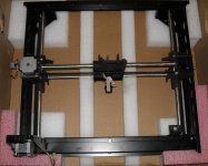
Work on Coil Winder
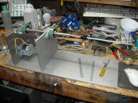
I've had a little time to get back to the coil winder. I completed machining the main (belt) drive mounting plates and bearing support. Next will be the angle brackets to hold the vertical walls to the base. Then the wire feed traverse. I hope to have enough room for the power supply and electronics inside the housing.
I also gave up on buying any more polystyrene Q-dope and bought a can of Toluene.My 4oz bottle had dried up. the toluene was cheaper than mail ordering a 4 oz bottle of Q-dope. I now have about 8oz of polystyrene glue settling.
I have been doing research on vacuum varnish impregnation and have concluded it might be good for a power transformers or motors, but not an audio transformer. The reason is the dielectric constant of almost all of the available varnishes made for this purpose is very high, in the range of 3.5 - 6.5.
Attachments
I've had a little time to get back to the coil winder. I completed machining the main (belt) drive mounting plates and bearing support. Next will be the angle brackets to hold the vertical walls to the base. Then the wire feed traverse. I hope to have enough room for the power supply and electronics inside the housing.
I also gave up on buying any more polystyrene Q-dope and bought a can of Toluene.My 4oz bottle had dried up. the toluene was cheaper than mail ordering a 4 oz bottle of Q-dope. I now have about 8oz of polystyrene glue settling.
I have been doing research on vacuum varnish impregnation and have concluded it might be good for a power transformers or motors, but not an audio transformer. The reason is the dielectric constant of almost all of the available varnishes made for this purpose is very high, in the range of 3.5 - 6.5.
You can use wax (stearine, dielectricum=2.3)
Wax is also easier to use because you don't need a vacuum (just heat, 80-100˚Celcius)
Last edited:
a tighter winding raised the bar from about 0.50mH to 0.57mH
Warning that it also increases parasitic capacitances and proxi effect, both of them prejudice high frequency performance. :-D
- Status
- This old topic is closed. If you want to reopen this topic, contact a moderator using the "Report Post" button.
- Home
- Amplifiers
- Tubes / Valves
- Designing an Interstage Transformer