I do hope you won't ignore the XquiSIT (or whatever will be named the VFet SE design).I will be talking briefly about both the DEF and the DEFiSIT, and bringing
working copies of each.
Can't wait for the schem!
Experimenting with DEF wired in a Common Gate Configuration
The attached schematic describes the application under study. Note the following construct:
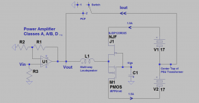
1 DEF is idealized for simplicity. It is comprised of SJDP120R085 N-JFET and its match IRFP9140 P-MOSFET. Their gates are joined and biased by a common negative Vgs which is AC grounded [meaning common gate].
2. My DEF on the bench idles at +/-1.5A from a +/-17 V PSU which is a simplified classical rectifier circuit.
3. The joined sources of the FETS is the input to DEF; meaning it accepts current and lots of it [limited by bias].
3. An integrated power amp [IPA] is the source of power current that is pushed through the joined sources of DEF.
4. The integrated power amp driving the DEF can be/is your choice as shown. Mine is a utility compact SONY which delivers ~10 W/8 Ohms I used to demonstrate the concept. It has controls for volume and independent tone, plus miscellaneous input sources, AM, FM, CD tape Video [aka Aux in this case].
5. The current which enters the joined sources of the FETs in DEF exits in its entirety at their joined drains. The exit port of DEF's AC current is the center tap of the dual polarity PSU's power transformer as indicated.
Here's how it works. It does so cleanly without any oscillation or problems.
1. A loudspeaker is connected in series [inserted] between the power output port of the integrated amp [IA] and the joined sources of DEF.
2. The ouput current of IA enegizes the loudspeaker, it enters the joined sources of the FETs and exits in phase and in its entirety [magnitude] at their drains as described above.
3. I gave the output current two choices via the shown toggle switch. Dump it to ground[1] or send it back [2] to the power output port of [IA] as Positive Current Feedback [PCF].
4. It is important to note that the exit current of DEF be it PCF or grounded must return to the PSU of the integrated amp where it originated in the first place. This PCF current will not make a second pass through the loudspeaker and continue to recycle indefinitely.
5. With PCF engaged, the power output of the integrated amp is "bootstrapped". This has the benefit of increasing the actual impedance of the loudspeaker[possibly doubled], plus causing other potential and beneficial sonics.
Enjoy the crisp and clean sound of this arrangement.
The attached schematic describes the application under study. Note the following construct:
1 DEF is idealized for simplicity. It is comprised of SJDP120R085 N-JFET and its match IRFP9140 P-MOSFET. Their gates are joined and biased by a common negative Vgs which is AC grounded [meaning common gate].
2. My DEF on the bench idles at +/-1.5A from a +/-17 V PSU which is a simplified classical rectifier circuit.
3. The joined sources of the FETS is the input to DEF; meaning it accepts current and lots of it [limited by bias].
3. An integrated power amp [IPA] is the source of power current that is pushed through the joined sources of DEF.
4. The integrated power amp driving the DEF can be/is your choice as shown. Mine is a utility compact SONY which delivers ~10 W/8 Ohms I used to demonstrate the concept. It has controls for volume and independent tone, plus miscellaneous input sources, AM, FM, CD tape Video [aka Aux in this case].
5. The current which enters the joined sources of the FETs in DEF exits in its entirety at their joined drains. The exit port of DEF's AC current is the center tap of the dual polarity PSU's power transformer as indicated.
Here's how it works. It does so cleanly without any oscillation or problems.
1. A loudspeaker is connected in series [inserted] between the power output port of the integrated amp [IA] and the joined sources of DEF.
2. The ouput current of IA enegizes the loudspeaker, it enters the joined sources of the FETs and exits in phase and in its entirety [magnitude] at their drains as described above.
3. I gave the output current two choices via the shown toggle switch. Dump it to ground[1] or send it back [2] to the power output port of [IA] as Positive Current Feedback [PCF].
4. It is important to note that the exit current of DEF be it PCF or grounded must return to the PSU of the integrated amp where it originated in the first place. This PCF current will not make a second pass through the loudspeaker and continue to recycle indefinitely.
5. With PCF engaged, the power output of the integrated amp is "bootstrapped". This has the benefit of increasing the actual impedance of the loudspeaker[possibly doubled], plus causing other potential and beneficial sonics.
Enjoy the crisp and clean sound of this arrangement.
Attachments
I will be talking briefly about both the DEF and the DEFiSIT, and bringing working copies of each.
Lucky Diyers who can be at BAF17 an hear this hot new amplifiers.
The full silicon carbide DeFiSIT are extraodinary i guess.
Interested by schematic with obtainable parts.
Festival it's start happen after tomorrow
")
Attachments


ValDEF - Valve DEF buffered amplifier
For me, the DEFiSIT output stage is simply the most beautiful topology. Thank you Mr Pass for sharing with us.
Since tubes are more accessible for many of us compared to the SIT transistors, I adapt the DEF biasing scheme and sim a tube as input to an enhancement N MOSFET and P Lateral MOSFET pair and get very good results beyond expectation.
Triode transfer function, 0.081% THD at 1W into 8 ohm, negative phase H2 dominant, monotonic distribution. 100k input impedance, 9.94 DF. -1.47dB (0.84) gain, clipping at 19V input, 16V output, ~15W output with 180V and bipolar 23v PSU.
Attachments
For me, the DEFiSIT output stage is simply the most beautiful topology. Thank you Mr Pass for sharing with us.
Since tubes are more accessible for many of us compared to the SIT transistors, I adapt the DEF biasing scheme and sim a tube as input to an enhancement N MOSFET and P Lateral MOSFET pair and get very good results beyond expectation.
Triode transfer function, 0.081% THD at 1W into 8 ohm, negative phase H2 dominant, monotonic distribution. 100k input impedance, 9.94 DF. -1.47dB (0.84) gain, clipping at 19V input, 16V output, ~15W output with 180V and bipolar 23v PSU.
Knowing zero and less about tubes I still must ask
Would the Korg tube work here?
Bob
The attached schematic describes the application under study. Note the following construct:
1 DEF is idealized for simplicity. It is comprised of SJDP120R085 N-JFET and its match IRFP9140 P-MOSFET. Their gates are joined and biased by a common negative Vgs which is AC grounded [meaning common gate].
2. My DEF on the bench idles at +/-1.5A from a +/-17 V PSU which is a simplified classical rectifier circuit.
3. The joined sources of the FETS is the input to DEF; meaning it accepts current and lots of it [limited by bias].
3. An integrated power amp [IPA] is the source of power current that is pushed through the joined sources of DEF.
4. The integrated power amp driving the DEF can be/is your choice as shown. Mine is a utility compact SONY which delivers ~10 W/8 Ohms I used to demonstrate the concept. It has controls for volume and independent tone, plus miscellaneous input sources, AM, FM, CD tape Video [aka Aux in this case].
5. The current which enters the joined sources of the FETs in DEF exits in its entirety at their joined drains. The exit port of DEF's AC current is the center tap of the dual polarity PSU's power transformer as indicated.
Here's how it works. It does so cleanly without any oscillation or problems.
1. A loudspeaker is connected in series [inserted] between the power output port of the integrated amp [IA] and the joined sources of DEF.
2. The ouput current of IA enegizes the loudspeaker, it enters the joined sources of the FETs and exits in phase and in its entirety [magnitude] at their drains as described above.
3. I gave the output current two choices via the shown toggle switch. Dump it to ground[1] or send it back [2] to the power output port of [IA] as Positive Current Feedback [PCF].
4. It is important to note that the exit current of DEF be it PCF or grounded must return to the PSU of the integrated amp where it originated in the first place. This PCF current will not make a second pass through the loudspeaker and continue to recycle indefinitely.
5. With PCF engaged, the power output of the integrated amp is "bootstrapped". This has the benefit of increasing the actual impedance of the loudspeaker[possibly doubled], plus causing other potential and beneficial sonics.
Enjoy the crisp and clean sound of this arrangement.
is L1 a audio transformer ?. little bit confused due to technical terms?. Please someone explain little more.
is L1 a audio transformer ?. little bit confused due to technical terms?. Please someone explain little more.
Hello Nag. My apology for any confusion I caused. L1 is my model for a loudspeaker which maybe full range or multiway.
Hello Nag. My apology for any confusion I caused. L1 is my model for a loudspeaker which maybe full range or multiway.
Dear Antoinel,
Thank you for clarifying. Actually your post is clear, I am confused with previous posts and DEF slide in BAF2017 which has transformer.I thought where it has gone.
We know you are very busy with DEFiSIT.
Can we replace deferential amplifier U1 R1 R2 R3 with headphone amp which has 0.5 ohm and 7 Vp-p voltage ?. Center tap of PSU is ground how it is working as PCF ?.
I have very limited knowledge on electronics thats why I am asking. Thank you.
As a concept yes, but finding Vgs matches at 1.5 A at temperature between
a depletion mode part and an enhancement mode is tedious at best.
The R085's are in spitting distance of common P channel enhancement mode
parts like Fairchild, IR, and Harris, and even then it took me a couple days to
get a small batch.
Of course I was shooting for no degeneration and no adjustment...
Mr. Pass,
How tightly matched at 1.5A? How long to get to temp? Was it the normal 1 hour or so like for power amps?
Thx,
Vince
I test them on a heat sink pre-heated to 50 deg. C. which speeds up the
process, and I still have to give it a minute or so.
As to tolerance, the ballpark you are looking at is dependent on the
transconductance, which is around 2 S. or so, the equivalent of .5 ohms.
So a .1V tolerance is about 200 mA - actually more like 100 mA if shared
between two devices, where the "apparent" resistance is about 1 ohm.
Dear Antoinel,
Thank you for clarifying. Actually your post is clear, I am confused with previous posts and DEF slide in BAF2017 which has transformer.I thought where it has gone.
We know you are very busy with DEFiSIT.
Can we replace deferential amplifier U1 R1 R2 R3 with headphone amp which has 0.5 ohm and 7 Vp-p voltage ?. Center tap of PSU is ground how it is working as PCF ?.
I have very limited knowledge on electronics thats why I am asking. Thank you.
Hello Nag. I have one more post to publish on using DEF in a common gate configuration. I hope that it will be informative and answer your very good questions above. Have you assembled a DEF?
- Home
- Amplifiers
- Pass Labs
- DEF Amp