
I have added a connection to the trafo for positive current feedback [PCF] and/or boostrap.
Imaginative. I like it.

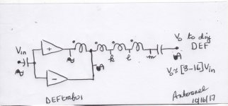
Hi claudio52. I am looking forward to all of the BAF 2017 goodies.The building blocks in the attached schematic [buffer, trafo, DEF] have already been taught by Pass. Note that a direct current is not allowed to flow through the trafo windings. I have added a connection to the trafo for positive current feedback [PCF] and/or boostrap.
Best
Anton
Hi Antoinel
Trafo PCF and/or bootstrap connection for DEf and Vfet amplifier's that superb interesting option

***** Have a nice day
 *****
*****
The attached schematic shows another circuit for an auto-former passive gain block. The primary winding of the auto-former is wired as a bridge tied load [BTL] to/of two preamplifiers; whereby their two output signals driving the primary winding it are 180 degrees out phase. The output voltage [Vo] of this auto-former circuit to the input of a diyDEF may range between [8-16] times that of Vin.
The Pass preamplifier described by DIYer juma in his thread "LSK pre-BAF 2013' has in principle 2 outputs which are 180 degrees out of phase with each other. It is most probably useable in this application. The value of the load resistor at its normal [inverted] output will need to be trimmed so as to make both output signals equal in absolute amplitude.
The Pass preamplifier described by DIYer juma in his thread "LSK pre-BAF 2013' has in principle 2 outputs which are 180 degrees out of phase with each other. It is most probably useable in this application. The value of the load resistor at its normal [inverted] output will need to be trimmed so as to make both output signals equal in absolute amplitude.
Attachments
trouble (or beauty) is in fact that something somewhere must be referenced to ........ something
in most situations to GND , but not necessary
where is ref. point for amp itself ?
Hi Zen Mod. My apology for not calling the schematic "simplified". I should have been more explicit as follows. Thanks for your constructive comment.
The non-inverting [LSK] preamp output is the joined sources of the input complementary JFETs which connect to ground via a suitable resistor. The voltage gain at the joined sources of the input JFETs is unity.
The inverting [LSK] preamp simultaneous output is the joined collectors of the complementary BJTs connected in a folded cascode configuration. This junction of opposed BJT collectors goes to ground via a second resistor which determines the inverted output gain of the inputsignal .
The value of this second resistor needs to be lowered so as to deny this second [folded cascode] stage a voltage gain and essentially make it unity. Thus both outputs will have identical unity gain for their respective Vout; but are 180 degrees out of phase.
The joined gates of the front end complementary JFETs are connected to ground via a resistor which determines the input impedance to Vi which is referenced to common or ground.
I built 10 copies, currently being played with by my listeners.
An article is forthcoming, and I'm considering a kit.
and no unobtainium parts?!?!?
SemiSouth R085's and Toshiba Jfets.....
Lol.
As a concept yes, but finding Vgs matches at 1.5 A at temperature between
a depletion mode part and an enhancement mode is tedious at best.
The R085's are in spitting distance of common P channel enhancement mode
parts like Fairchild, IR, and Harris, and even then it took me a couple days to
get a small batch.
Of course I was shooting for no degeneration and no adjustment...

- Home
- Amplifiers
- Pass Labs
- DEF Amp