The DEF versions I have laying around here use either the Jensen or Cinemag
transformers for 12 dB step up. If the output of your PC card has an
output impedance lower than 50 ohms or so, it should drive it OK.
So as per my understanding we are are using step-up transformer converting 2Vrsm*12 dB=+24Vrms feed into DEF amp.Please correct me If I am wrong.

As I understand it a close-enough rule-of-thumb is that each 3dB is 2x. So 12db would be 16x (four doublings).
Maybe power but not voltage.
12dB = 4x voltage gain.
Maybe power but not voltage.
12dB = 4x voltage gain.
I guess we're always relating to SPL ratios (ie: power) rather than amplitude (ie: voltage), and P varies with V^2. Since ^2 equates to 2x on a logarithmic scale, it takes 6dB of voltage for each doubling?

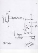
if you say 1:1 , that's usually thingy with two identical (in ratio) windings
what you drew is classic telephone repeater coil , usually marked as 1+1:1+1 , which can be connected as 1:1 , but also in few different ways
so , drawing is OK < while nomenclature you used is not
btw - using top rail as reference will bring all drek from rail to gates
it's logical to do that when modulation of output device is also referenced to rail , which isn't case here
in short - bring C1 to GND
Last edited:
Perhaps a 1:1 transformer can be used.
View attachment 639141
Hi claudio52. I'm glad to see that you're still working with DEF. The trafo arrangement that you show in your schematic is like or the same as shown by Mr. Pass in his schematic of post#96 in the thread "What to with those 2SJ28s". Neat.
Best
Hi Antoinel,copy and paste is exactly that. Simulation is incorrect because the parasitic elements of the real trasformer are not present. Better wait the Burning Amp ( Nov 12 ).
Hi claudio52. I am looking forward to all of the BAF 2017 goodies.The building blocks in the attached schematic [buffer, trafo, DEF] have already been taught by Pass. Note that a direct current is not allowed to flow through the trafo windings. I have added a connection to the trafo for positive current feedback [PCF] and/or boostrap.
Best
Anton
Attachments
well, I was opponent of bias going through windings, but Pa did exactly that in F6
Hi Zen Mod. The generalized DEF section requires independent controls over its idle current [due to the difference in the Vgs values of its FETs], and to minimize its output DC offset to <+/-50 mV.
If the FETs in the Pass DEF have exactly the same values for Vgs [very high probability] , then the adjustable resistors in the DEF section may not be/are not needed. His schematic becomes similiar to that of SIT-3 whereby the bias for Vgs is coupled directly through the trafo. But; a blocking cap will still be needed at Vin, and another one for PCF/boostrap [if used].
Best
Anton
- Home
- Amplifiers
- Pass Labs
- DEF Amp