kostazl said:How about that Re-design of the idea ...
With Multisim 8 gives from 1 to 50W THD<0.01% @ 4 ohms (20Hz-20kHz).
The Darlingtons can be any transistors with the desired parametrics.
.
Looks very, very good, kostazl
A possible variation version of DoGC.
How this compares to widowmaker's original, I guess nobody knows?
You think it is an improvement, kostazl?
What figures you get if simulating the DoGc original circuit?
Regards
lineup
")
I like it, especially bootstrapped class-A section and buffer before it. I think that original schematic with mosfets would benefit from buffer too. What is a purpose of 1uF cap in buffer's collector? To reduce C-E and B-E capacitance effects? BTW I think that when using darlingtons, we can put three diodes, not two. That way we'll be closer to class B bias.kostazl said:How about that Re-design of the idea ...
With Multisim 8 gives from 1 to 50W THD<0.01% @ 4 ohms (20Hz-20kHz). The
Darlingtons can be any transistors with the desired parametrics.
There are some variations of widowmaker's original design suggested by me earlier in this tread as possible improvements. Well, one of those ideas was recently done practically by me and it is performing extremely well on my bench for last month and a half for several hours every day! I can't say what are comparative advantages (if any?!) in regards to original design, because I never got a chance to have working original unit to compare, but if that original is working like this my version, it is a hell of a "machine".
For now I will post here only schematic. PCB design and layout I won't post without widowmaker's permission because this is his tread, it seems he is making some money from this design and by publishing PCB and layout files I will express disrespect to my fellow colleague designer. If that is OK with him, I can post those files as a gift for all of you, because I am not making money from DIY activities.
For now I will post here only schematic. PCB design and layout I won't post without widowmaker's permission because this is his tread, it seems he is making some money from this design and by publishing PCB and layout files I will express disrespect to my fellow colleague designer. If that is OK with him, I can post those files as a gift for all of you, because I am not making money from DIY activities.
Attachments
boraomega said:There are some variations of widowmaker's original design suggested by me earlier in this tread as possible improvements.
Well, one of those ideas was recently done practically by me and it is performing extremely well on my bench for last month and a half for several hours every day!
I can't say what are comparative advantages (if any?!) in regards to original design, because I never got a chance to have working original unit to compare,
but if that original is working like this my version, it is a hell of a "machine".
-------------
.
thanks bora
I remember you have posted several interesting versions
of this circuit, earlier in this thread.
This latest schematic from you, I like.
I am sure it is an improvement in some details of 'original DoGC'.
widowmaker likes it fairly simple,
this can be a good approach in some ways (easier to understand and build) and less good in other aspects
thanks again
lineup
Well, i just need to give you another view of the idea. The reason is that I did so many simulations around the Quad405, the original current dumping topology, the flatest mods (like 306 and 606) and even the very popular mod in my country, wich you can find at http://www.constructor.bg/mk/Amp.htm. The last one is very unstable and goes to oscilations every time when is overheating or you try to use newer transistors.
God knows how many times I've tried to improve it, and again the result was excelent distortion figure, with second harmonic dominant, until you go into clipping. Then you realise that this topology works only in the way, used by The QUAD manifacturer.
I respect very much Windowmaker (at least he is from BG as well),
but this path is already lost.
There is another way and i will show you some day ....
Good luck my friends ....
kostazl
sorry to hear your troubles with your version
I am sure you will come up with a good solution
.. maybe even some little improvement to widowmaker / boraomega versions!
keep on trying
I will be here to see what happens
regards
lineup
'PS. I use EWB MultiSim to simulate amplifier circuits.
There is a working torrent download of MultiSim
try search google:
torrent multisim v9
DS.
Hi "kostazl",
My version published a few posts earlier doesn't show any trace of tendency toward self-oscillations at all no matter what is the temperature or is it clipping?! Frankly, my speakers are relatively benign regarding reactive behavior and that could be one of possible reasons. Another could be PCB layout and eventual mutual influence between 4,5uH coil and surrounding components?!
I am rarely pushing an amp into clipping because it is not primarily designed to work under such conditions. If amp is performing marvelously on all levels under onset of clipping, with good sound in any aspect and perfectly stabile, why will I ever need to push it further?! I will use it through entire "working life" of that unit well within its designed limits and it will perform as it is expected. Fact that I maybe won't know how it is behaving during clipping won't diminish my pleasure and enjoyment with that amp.
If your car have red zone above 6000RPM on a RPM-meter, what on Earth is suppose to force you to press accelerator pedal for more than that... except if you are interested to see pistons popping out through bonnet on the street!? That test won't prove any way, that your car is not good.
Of course, that is just MY point of view... others won't have to agree!
Re: My point of view is the same Bora.... pushing things hard
Very right you are, Carlos, as is Bora, too
We do not build amplifiers
for even getting near to clipping conditions
We build amplifiers, to enjoy music
at a reasonably 'normal' listening level.
If you are into running your own Disco Music Club
in your city,
You should not consider some HifI amplifier, like DoGC in this Topic.
There are plenty of better options for PA-amplifiers, for DJ applications, too
in other topics and websites.
---------------------
* PA Amp = Public Announcement Amplifier
... amplifiers to reach many people in a crowd
... maybe outdoors or in such places as Madison Square Garden ... and such
The main goal here is NOT Audiophile HIFI,
but The Main goal is maximum LOUDNESS, most often in a more narrow audio freq band.
Regards
lineup
Lineup Audio Labs - News!
http://lineup.awardspace.com/
destroyer X said:
will not result good.
regards, Carlos
Very right you are, Carlos, as is Bora, too
We do not build amplifiers
for even getting near to clipping conditions
We build amplifiers, to enjoy music
at a reasonably 'normal' listening level.
If you are into running your own Disco Music Club
in your city,
You should not consider some HifI amplifier, like DoGC in this Topic.
There are plenty of better options for PA-amplifiers, for DJ applications, too
in other topics and websites.
---------------------
* PA Amp = Public Announcement Amplifier
... amplifiers to reach many people in a crowd
... maybe outdoors or in such places as Madison Square Garden ... and such
The main goal here is NOT Audiophile HIFI,
but The Main goal is maximum LOUDNESS, most often in a more narrow audio freq band.
Regards
lineup
Lineup Audio Labs - News!
http://lineup.awardspace.com/
I am very disappointed, that you've got me so wrong, gays...
I am also audiophile as you are, but nobody, absolutely no body can convince me that good engineered amplifier can give unstable clipping, because that means it will die as soon as you reach the clipping zone.
Everybody knows, that listening to dynamic modern music, Jazz or even Classics are often putting the amplifier near to clipping conditions. This effect is many times worst when your supply is with bad regulation or with less power capability. Never forget the logarithmic transitions of the real audio signal.
And just let me know how many of you actually built that amplifier and tested it ...
Well, some of you may say that I am only using simulating and talking bullshits, but those of you, who are using Multisim knows how precise all the models are. And all of my QUAD405 mods (which are all death now) gave me bad clipping during the simulation, but the rebuild of the original schematic is still working.
Better modification target could be the QUAD303’s topology!
I am not blaming anybody, it’s just may opinion according to my experience! I may be wrong but nobody gives me a good stable argument!
kostazl said:I am very disappointed, that you've got me so wrong, gays...
I am also audiophile as you are, but nobody, absolutely no body can convince me that good engineered amplifier can give unstable clipping, because that means it will die as soon as you reach the clipping zone.
Everybody knows, that listening to dynamic modern music, Jazz or even Classics are often putting the amplifier near to clipping conditions. This effect is many times worst when your supply is with bad regulation or with less power capability. Never forget the logarithmic transitions of the real audio signal.
And just let me know how many of you actually built that amplifier and tested it ...
Well, some of you may say that I am only using simulating and talking bullshits, but those of you, who are using Multisim knows how precise all the models are. And all of my QUAD405 mods (which are all death now) gave me bad clipping during the simulation, but the rebuild of the original schematic is still working.
Better modification target could be the QUAD303’s topology!
I am not blaming anybody, it’s just may opinion according to my experience! I may be wrong but nobody gives me a good stable argument!
I am sorry, kostazl
Yes, I got you wrong
I write my posts not for only one person
but for anybody that might pop in here.
Maybe someone else can get something to think about.
I like Jazz very much .. Acoustic music
with natural recordings techniques.
Like for example such high class recordings those of 'Cardigans' ( 'Love Fool' .. etc )
===============================
And in a world of digital manupulations and artificial processing
... this little label is Just precious
Opus3Records.com - philosophy!
Opus 3's recording technique has been specially developed for acoustic music
and is based on using the natural acoustics of authentic environments such as churches, concert halls, jazz clubs and so on.
We match the venue to the music, so to speak, as opposed to the common studio practice of adding an artificial reverberation afterwards and so on. The positioning of the microphone in the recording room and the positioning of the musicians in relation to the microphone are also extremely important.
From the very outset we have used what is known as the coincident or X/Y recording technique, mainly employing the special configuration of crossed figure of eights, also known as the Blumlein technique, after Alan Dower Blumlein, the British radar engineer who developed the technique way back in 1934.
Depth of Image
So accustomed are we to three-dimensional vision, that we never really think about it. But we need only shut one eye for our judgment of distances to be reduced and our three-dimensional vision to disappear: we need both eyes and the relation between them in order for see three-dimensionally. Much the same is true of our hearing.
Our brain and auditory system "process" the sound-waves reaching each ear, with regard to level, direction, time and frequency content. The signal is further "analyzed" by our brain and auditory system, and the differences between signals coming from our two ears tell us, for example, about distance to the different sound sources and their relative positions. We experience "Depth of Image": for example, the different instruments of the orchestra in a concert hall are differently placed, not only from left to right but also in depth, together with the size and acoustics of the concert hall.
Opus3 Catalogue Contents
Very much Regards
to everybody reading
lineup
Lineup Audio Recordings Home Studios
my version, it is a hell of a "machine".
Dr.Bora,
Is your schematic complete as posted and is it possible for one to build a trouble-free working model on that basis?
Tell us more about its sonics!!
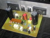
Absolutely Samuel! That schematic is exactly the version I kept finally and is actually working on my bench for last several weeks. As soon as my younger daughter is back from holiday trip to Italy (she got my digital camera!), I’ll try to make and post some pictures here.
As I said previously, Iwill NOT post PCB and layout files here because this is “widowmaker” tread, but anyone interested to try my version is free to contact me on my E-mail address available in my profile. Those files are FREE for anyone for personal use!
Kostazl, your countryman's nick is "widowmaker" and not "windowmaker", even thou some windowmakers could easily become widowmakers if they try hard!
Boraomega, I am interested in getting the PCB design and trying out this amp.
In the meantime, here are a couple of questions.
1) Would it be possible to use two pairs of 2SC5200 and 2SA1943 transistors in place of the hard to get Sanken output devices? If the answer is yes, what would be the value of the emmiter resistors?
2) What are the devices under the small copper-coloured heatsink on the PCB?
3) From the picture posted, some of the resistor values don't seem to correspond with parts shown in the schematic!! But I could be wrong here.
Hello boys,
First of all, to my taste, it would be really inappropriate to hijack "widowsmaker" tread and start answering questions and post PCB-s and layouts! As I stated before, most of my work (designs, PCB-s, layouts etc.) are available FREE for DIY community and personal use, but everyone interested would have to contact me on my E-mail address: kia-ora(at)blueisp(dot)co(dot)yu
Please don't get me wrong! I want to avoid to be seen as rude and disrespectful to my fellow colleagues.
Hi all,
I read whole topic from the first page. However I couldnt understand what happened to 4,5$ first design? Sorry for poor English!
I made three gainclones, (I dont like them) and one LM4702 with Renesans MOSFETs.. I like its sound too much. But its a 150W amplifier and too big for me, it takes a lot of spaces in my living room. Because of WAF I must get retired him.
Anyway, these are my personal problems. What I want from you is; some help to make a good sounding (better than gainclones and LM4702) and more acceptable size amplifier for my living room. And I supposed that DOGC (first version) was a shiny idea for that position...
However I see that, there are a lot of version of it! I want a tiny size, simple, includes available parts (like BD911 etc..), really good sounding amplifier.
May somebody tell me which version should I use? Or what happens if I use the first one? May I get "pure" sound from it? Or you advice another one?
Thx in advance.. (with YTL)
- Status
- This old topic is closed. If you want to reopen this topic, contact a moderator using the "Report Post" button.
- Home
- Amplifiers
- Solid State
- Death of Gain Clone