Ciao plovati,
Yes, you have the right picture. Like rolling up a capacitor, two sheets rolled up at once. The flux in the soft magnetic material, or M6, does indeed go along its length, but when it crosses the gap from layer to layer to make a loop, it does so in the orthogonal direction while in the gap. So the magnet layer with orthogonal field should be just fine.
Don
gosh! its a flux capacitor!
Gee, I was just thinking. If it looks like a capacitor, and acts like a flux capacitor (cancels DC field), well, you know the saying: It IS a flux capacitor. We can call the interleaved toroids "flux capacitors"!
Imagine telling your friends that your amplifiers have "flux capacitors" in them! (assuming you all saw the movie "Back to the Future")
Don
Physics 201 tutorial
Just a few more words on the magnetic field path in wound toroid cores. Whenever a field line leaves a high Mu material to enter low Mu air, it does so at right angles to the surface. This is similar to electric field lines leaving a conductor into air. The high Mu material acts as an equipotential in the field. (for only slightly different Mu materials, the rule is the same as "Snell's law" for optical materials with differing index of refraction, the law of sines or cosines depending on your point of view) Some text books actually have a detailed diagram of the flux lines around a wound toroid core, and the lines do indeed have a jagged right angle notch in the gap.
Can also think about the field lines of the permanent magnet sheet interleaved between the soft iron or M6 sheet. The field lines leaving the magnet sheet at right angles must find a path to return to the opposite side of their sheet to complete a flux loop. (all magnetic fields form loops unless you have managed to round up some monopoles, in which case let me know so I can get off the planet fast. They would continuously accelerate in the Earth's field, bad news) The only way for the flux to get around to the back is to go around thru the M6 sheet for a turn.
Don
Hi Piergiorgio
I've digged a bit around your idea, trying to design the OPT.
At first, it seems that 1000 turns on an 1sqi is a bit optimistic and I had to go up to near 1700 turns to keep AC induction below 1.2 tesla for 25Hz at 8W. This using a 7.2cm² core (EI84A), M6X grade iron.
It remains acceptably small and provides some extra space in the copper window to accept the "DC cancel" winding.
For now, my guesses are:
4 primary sections, each in four layers of 103 turns, wire dia 0.28mm.
All in serie, 80 Ohms DCR, 160Hy ( ! ! )
Interleaved with 5 secondaries, each in one layer of 84 turns each, wire dia 0.4mm, all in paralell, 0.4 Ohms DCR.
The thickness of insulation at primary to secondary boudaries being 0.3mm.
Estimated leak inductance in the 5Hy range.
Above that, the DC cancel winding, 1648 turns wire dia 0.2mm, some 170 Ohms DCR.
There is less than 160v rms accross it, so no special insulation need to be inserted between layers.
Well, all that to check if the OPT was feasible, I think it is.
Not yet worked on the choke.
And after that, perhaps a full prototype ?
Yves.
Smoking-amp:
I'm playing with vizimag to see the fields on some geometries. Maybe yours idea of rolling togheter a soft magnetic sheed and a magnet can work. My guess is the rubber magnet are not strenght enough and has too low coercitive field.
Better is to roll togheter two sheet one of soft iron and the other of some hard magnetizable medium and after winding the coils magnetize the hard magnetic material. I do not Know how to magnetize it in the radial direction.
Yves:
I think that this arrangement (Farber modified) is worthing most for low plate resistance high current tubes, I'm thinking on a 6080PSE. True that the simulation is not considering the flux level (actiually was 1 squared cm, not inch!), but just the inductance.
Yes, I think a test bed for this solution can be a good experiment.
Re: Physics 201 tutorial
i still don't see how this helps things out. the magnet layer inbetween the core material layers will take up space (thus reduccing your core area) and since it will have a perm of 1 will effectively increase the size of the airgap in the core.
the loss of perm from the larger airgap can only be offset if the magnet has a perm of more than 1, but then it becomes a soft magnetic material.
am i missing something?
dave
smoking-amp said:Just a few more words on the magnetic field path in wound toroid cores.
i still don't see how this helps things out. the magnet layer inbetween the core material layers will take up space (thus reduccing your core area) and since it will have a perm of 1 will effectively increase the size of the airgap in the core.
the loss of perm from the larger airgap can only be offset if the magnet has a perm of more than 1, but then it becomes a soft magnetic material.
am i missing something?
dave
Ring magnetic compensated core
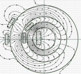
I see a bigger problem: because the magnetization of PM sheet is radila, the flux in two adjacent soft magnetic sheet is opposite, so half the core is prepolarized in one direction and the other half at the contrary. Because turns are wind over both the core, half of it will be forced in saturation.
See this schetch:
Attachments
Hi Piergiorgio,
Your model is not using a spiral wind of soft magnetic material. Concentric rings will indeed fail to work, no surprise there. Also, the magnet needs to be a continuous spiral too. The spiral pattern gives the flux a path around the ring of high Mu to follow, so field lines will largely stick to the sheet instead of taking air pathes. The concentric circles has no high Mu path around so all the field lines are jumping out into air. Also, the magnetic material should be very thin so the effective gap for a lamination will be small.
Hi Dave,
Yes, the Mu=1 magnet layer does act as a gap. However, we have a powerful advantage here due to the spiral geometry. One whole turn of the sheet is the gap area (and the magnetic sheet thickness the gap length) for one lamination layer. Magnetic gaps are just like resistances. Large area is equivalent to paralleled resistances. Gap length is like the value of resistors. Looking at the area of the one turn sheet versus the cross section area of the soft lamination, I'm guessing we have something like a 1000 to 1 ratio. This means the gap length effectively gets reduced in length by 1000. So would be equivalent to a single conventional gap cut in the core of the sheet thickness divided by 1000. This distributed gap effect is the reason toroidal cores have better effective Mu than E - I cores.
We also get the advantage of the large are of the magnet sheet for accumulation of a large amount of magnetic flux to pass thru the single lamination (1000x gain again). So the magnet layer does not need to be Neodymium or something exotic. But it should still be thin. Have to crank the numbers for a real magnet material.
Don
Hi Piergiorgio,
"Better is to roll together two sheet one of soft iron and the other of some hard magnetizable medium and after winding the coils magnetize the hard magnetic material. I do not Know how to magnetize it in the radial direction."
If some magnetizeable sheet can be found this should work fine providing the magnetizing field does not need to approach or exceed the saturation level of the soft material. The field applied would be the same as from a winding on the toroid, not radial. The reason being, is that the field lines will follow the spiral soft material and jump across the hard material at right angles just like in normal operation, as long as the soft material is still reasonably higher Mu than air.
Once the soft material saturates however, it will just be like air itself, so then the field lines will go longitudinally thru the magnet material as if all air core. This will not work if the magnetization goes longitudinal. I suspect that magnets get magnetized at near steel saturation levels or higher, so this may indeed be a problem. Maybe Neodymium has to use a superconducting magnetizer coil since steel pole pieces would just saturate.
A way around this would be to do the magnetization before winding into the final toroid form. One would pass the lamination material sequentially thru the magnetizer with a transverse field (ie thru the sheet orthogonally between magnetizer pole pieces)
Interestingly, a pre-magnetized material like this should practically wind intself up into a toroid! More likely to be a mess like sticky packing tape though!!
Don
Oh, how about mini de Lorean hubcaps for covers on the flux capacitors.
Here's another fabrication idea. Ferrite powder magnets have a nice advantage as far as magnetizing field required. These are simply crushed to powder and the powder gets aligned by a magnetic field before compressing in a binder. The crystals already have preferred magnetization directions, you just have to align them mechanically with the field.
I suggest starting with the pre-magnetized ferrite powder mixed in an epoxy binder. Paint or roller spread this stuff onto the soft lamination continuously and pass thru an orthogonal magnetic field to align the particles while the epoxy sets. Probably just have to pull the painted lamination continously over a bunch of permanent magnets on a long table with maybe a hot air environment to set up the epoxy quickly.
Don
Some sobering thoughts on the ferrite powder in epoxy technique. The alignment field still has to be very high here since it must overcome the local self interaction fields of the ferrite crystals in order to move them around. Maybe could get away with Neodymium magnets top and bottom around the lamination sheet to get this strength, not sure. Would need some serious engineering calculations.
Also, the epoxy needs to be a thin fluid for sufficient time for the particles to rotate around. Thick viscous stuff won't do. Heat applied to set up the epoxy needs to be after sufficient time is spent in the magnetizing field to align the particles. This is probably a process best left to some ferrite magnet manufacturer.
I would suggest as a first go around to try the thinnest layer available of refrigerator magnet, ferrite in rubber sheet, material. Need enough material to do at least one turn of the toroid lamination so one can make some performance measurenents.
Don
smoking-amp said:
I would suggest as a first go around to try the thinnest layer available of refrigerator magnet, ferrite in rubber sheet, material. Need enough material to do at least one turn of the toroid lamination so one can make some performance measurenents.
Don
hey don,
i see your point about the surface area of the gap reducing the length, still wonder if it would be small enough though.
I don;t think a fridge magnet is what you want, they are magentized in alternating lines NSNSNSNS across the face to essentially tyou have a bunch of N/S magnets in one sheet. From what i understand you are saying you need a strip magnet with N on one face and S on the other. The neodym strip heet magnet i had was just like this, (it wouldn;t stick to anything, but place it in a core and it would snap the core together) The backing (2mil poly) is a major space waster, but as you suggested if you simply bound it to the core tape then magnetized it across the faces you couls chew up a minimum of the window area.
any guesses what the stability of these magnets is over time?
dave
Hi Dave,
Whoa! I didn't realize the ****. magnets were magnetized in stripes, but that makes sense. They would stick better and it's probably easier to fabricate them that way.
Yeah, we would need a thin sheet magnet with all N on one side and all S on the other. You mentioned the neodymium sheet magnet, was it flexible? Where could we get some sheet magnet like it with all N on one side etc.? Maybe could strip the poly backing off with a solvent.
They used to make magnets with keeper bars so they wouldn't de-magnetize themselves with time. The thin sheet is probably the worst shape for long term stability. But maybe ferrite and neodymium are pretty permanent, I don't really know off hand. They should be stable once put into the wound up toroid since they effectively have a high Mu flux return path to act as a keeper then. Its the fringe fields around the edges that have opposite direction to the material that cause problems without the keeper path. But the electromagnetic DC field from SE operation will be opposing the material, so will be a powerful potential demagnetizing effect. Maybe need a strong "magnetize" field pulse from the winding at amplifier power up, sort of like the "de-magnetize" pulse used in TVs at startup.
I do have some books here so maybe I can find something on permanent magnet materials. What one really needs is a book on magnetic thin film materials. I know there are some. Since disk drives and re-writable CDs etc have a magnetic layer on them, there must be some way to fabricate thin magnet layers. Might be vacuum sputtered on or electroplated. I know some of the soft magnetic materials can be electroplated. Sure would be a convenient way, could put a magnetic film right on the M6 strip. I think there are some chromium alloys too, can certainly chrome plate things.
Don
smoking-amp said:Hi Dave,
Whoa! I didn't realize the ****. magnets were magnetized in stripes, but that makes sense. They would stick better and it's probably easier to fabricate them that way.
from what i understood back when i was looking into this, they make the material and then magnetize it for the appropriate use. I'm not sure how they do it, but they have two plates that they can place the appropriate fields on to magntize the strip so they can do N/S on the faces, NSNSNS in stripes and even opposing quadrants. The NSNSN magnets can be found by placing two together and sliding them against each other. In one direction you will feel them "skip" and as you rotate them the field strength will change drasticly. when the snap together, the stripes will be parallel.
Yeah, we would need a thin sheet magnet with all N on one side and all S on the other. You mentioned the neodymium sheet magnet, was it flexible?
yes! i looked back at my emails, and it was .004 magnet on a .004 backing to keep it in place and durable. I see no reason (other than $$$) why the supporting structure couldn't be the core tape. simply laminate the powder to the orthosil or whatever, then magnetize the whole unit. Essentially what it seems you want is a permanent magnet with a perm. bonding a permanent magnet to a soft magnetic material and coiling it seems to be just that.
Where could we get some sheet magnet like it with all N on one side etc.? Maybe could strip the poly backing off with a solvent.
I started at www.duramag.com and the sheet magnet came from www.edyne.com
I think you might be better off trying to get them to try some soft magnetic tape as the backing. Who knows maybe you can convince them its a patentable idea
But maybe ferrite and neodymium are pretty permanent, I don't really know off hand. They should be stable once put into the wound up toroid since they effectively have a high Mu flux return path to act as a keeper then.
cool point!
Its the fringe fields around the edges that have opposite direction to the material that cause problems without the keeper path. But the electromagnetic DC field from SE operation will be opposing the material, so will be a powerful potential demagnetizing effect. Maybe need a strong "magnetize" field pulse from the winding at amplifier power up, sort of like the "de-magnetize" pulse used in TVs at startup.
if you laminated your two layers, (the magnet material would work as an insulation to reduce eddy losses) and used a .004 layer magnet and a .012 tape, you would be at a 70% stacking factor and then couldn't you use a few hundred amps through a few turns of wire to form the magnet? the core material would act to form your N/S orientation to ideally oppose the current.
The best approach might be to source the neodym powder, then work with a tape core winder to fabricate the cores, I think we could handle the large current part
It seems alpha-core is in your neck of the woods....I know some of the soft magnetic materials can be electroplated. Sure would be a convenient way, could put a magnetic film right on the M6 strip.
Don
oops... i suppose i should read the whole post before i start a reply...
dave
duramag
edyne
be sure to at least check the last paragraph, it's a whopper
Hi Dave,
Looks like something could be put together. Thanks for the info. I just was throwing my $.02 cents in on this idea originally. I haven't even built a SE amplifier yet! If you guys want to pursue this thats fine with me (just cut me in on the patent too! but maybe better to just leave as public domain?) Would need to put a bit of money and effort into this to get it rolling I think. Then some tests to see how it performs and probably a few iterations back to the magnetics construction to get all the kinks out. I'd be happy to help out if needed. This is something one would pursue to get a manufacturable product. But is massive overkill for just a simple DIY project. A potential pitfall is if the magnetics drift in strength over time. This could end up requiring a complex control system to keep it tuned up. Just don't know until after you spend all the money on it.
As far as a DIY project to just build a SE amplifier with flux cancelation, I think there are easier ways than all this magnetics development. An idea I came up with recently is as follows.
The easiest way to do flux cancelation is to just use an extra inductor or current source in the various schematics mentioned. The current source is attractive due to its lower cost, but is a big waster of power. Fortunately there are some ways to build an efficient current source.
Using a Mosfet with a small ferrite inductor (air gapped) in series with its Drain output, we could use a PWM (pulse width modulation) chip to switch it at high frequency (say 100 KHz) to produce a regulated average current. Current sensing in either a source resistor or a current xfmr. provides feedback to the chip for average current control. A series resonant LC trap to ground (or B+) after the ferrite inductor (ie at the current source output) would be used to remove the switching frequency residuals before connecting to the SE tube amplifier. The Mosfet would have to be able to handle the plate voltage swings from the amplifier but would dissipate little power since it is either totally on or totally off.
No doubt some tubies will not like digital stuff going on though. One could clean this scheme up a bit by using a (say 100 KHz) carrier sine wave instead of PWM. And controlling for average current by DC bias of the Mosfet. The filter would then do a better job of cleaning up the output without any extraneous EMI generation. Wouldn't be quite as efficient as the PWM square wave, but still could be pretty good.
I myself lean toward the three channel (L, R, -L-R ) SE system with just a simple DC voltage controlled series bucking coil system (AC signals sum up to cancel out of the bucking voltage). This is a nice and simple scheme that adds a center channel which some people have liked for sound or can just ignore the L+R output.
A very, very interesting variation on this would be to use a single E-I core xfmr to do all 3 outputs on one xfmr. The L and R signals would use primary windings on the outer two legs of the E and the -L-R signal (with doubled DC bias) would use the center leg. The AC signals sum up correctly so no conflict in flux around the core occurs. The DC bias currents on the other hand cancel out, so no need for even the bucking windings. All automatic DC flux cancellation. Neat. Getting three outputs from one xfmr. looks pretty attractive to me (put secondaries over the primaries on each leg). This should make a good DIY project I think. Call it the "something for nothing" SE circuit! (in reality the three legs do have DC currents in them, but they all sum to give a N pole on the top of the xfmr. and a S pole on the bottom of the xfmr. The huge air gap from top to bottom of the xfmr thru the surrounding air forms the usual SE gap for limiting DC flux, and boy it will be limited with that big a gap. Hence, something for nothing.)
Don
Analysis of something for nothing
I've been thinking about the "something for nothing" circuit and have found it to be fascinating. It is capable of dual independent SE operation or dual P-P operation with controllable crossover.
With L, R, and -L-R signal channels driven by triode outputs (low impedance drive mode) any dissagreement between the zero sum of the three fluxes is forced across the huge air gap. (there is no air gap cut into the core, the air gap here is open air between the top and bottom of the xfmr.) So at low frequency the operation is essentially enforced as P-P for each L and R channel. I say P-P because the -L-R strongly interacts with the L and R channels. (there is no forced interaction between L and R however, the third leg of the E allows complete independence.)
As the frequency increases, the reactance of the air gap inductor will eventually become equal to the triode output impedances (actually its the L and R channel output impedances that matter) This begins to allow independent operation between the L, R, and the -L-R channel. So is a transistion frequency between P-P operation and SE operation. At high frequency, the -L-R channel becomes isolated by the gap reactance. (the L and R are already isolated by the third leg)
This transistion is of interest since many people prefer the slam of P-P operation for bass and the harmony of SE operation in the mid band. We can control this crossover frequency by adding a small inductor in series with the -L-R triode plate. Assuming a normal SE parafeed choke would be sized for 20 Hz -3dB, we would need about 1/10 of this inductance for a 200 Hz crossover or 1/100 of that inductance for a 2000 Hz crossover.
Since the three amplifier channels L,R and -L-R are all nominally linear amplifiers, what we ar really controlling is the effect of the -L-R channel to lower output impedance in rigid P-P mode and the freedom for even harmonics to exist in the outputs. The reactance of the air gap path and optional inductor controls how tightly things are knitted up or conversely how much slack is allowed.
A further interesting option exists yet. We can effectively control the air gap too! How? The -L-R channel is what is limiting access of residual flux thru the direct third leg (E core) path. By putting a pentode output here, using the same idle current as the triode before, we will now have a high impedance output on the third leg. This allows unregulated return flux thru the third leg, since the pentode output is insensitive to output voltage (or equivalently, flux thru the third leg).
This effectively allows complete independence of the L and R channels from the -L-R channel voltage, yet still preserves DC flux cancelling. So we now have two completely independent SE channels operating with DC flux cancellation. We can just call the pentode channel the DC flux compensator. By optionally providing an adjustable feedback path from the pentode plate back to its grid or to its driver tube (to set output impedance), we can control the ratio of SE or P-P operation at the low frequency end. So lots of flexibility here. And all using just a single normal E-I core for two sound channels. Hows that for something for nothing?!!?
Don
even more for nothing
I forgot to mention that we get the full bandwidth of a P-P xfmr even in dual SE mode. The AC signals see no air gap, so effective permeability of the core is just as high as in P-P design. This means the xfmr design should be capable of the same frequency bandwidth as a P-P design. Of course, this is just the advantage of DC flux compensation, so would be the same case in other DC flux compensated designs.
Just thought I should mention the original point of all this DC flux compensator business before losing sight of it in the fog.
Don
coming full circle
Sorry about being so long winded about all this, but I have just seen the light!
One can get the same benefits using a single double C core (or E-I core for that matter) for a single sound channel with DC flux compensated SE mode.
We just put the primary for the SE triode on one side of the double C core, and no air gap in the magnetics is required. The other side of the double C core gets a similar primary winding for use by a pentode. (actually they can both be on the same side, or just on top of each other too, whatever) The pentode operates as the DC flux canceler but with a small difference from the usual current source design.
For usual current source mode we would just put a fixed bias voltage on the pentode grid. Here, we will put the inverted audio signal on the grid. P-P you say. Not quite, there is a difference. If the pentode were a triode, yes, it would be P-P with two low impedance outputs. But with a pentode, its high output impedance does not force any voltage, only current. The triode is totally setting the output voltage by means of its internal Mu. The advantage we get using the driven pentode is free power output instead of wasted power in the current source. These must both operate in class A by the way.
This is very much like the distributed feedback schemes that use a partial cathode follower winding and a plate winding. We're just using triode plate for the low Z drive and pentode plate for the high Z drive.
The same features for a transition frequency from P-P at low frequency to SE operation at mid frequency can be obtained by a frequency selective feedback circuit on the pentode plate. Just have to change from low to high impedance output at some frequency. One can also adjust from P-P to SE mode over the whole bandwidth by a resistive feedback network on the pentode to set its output impedance relative to the triode's output Z.
OH, there is no reason this can't be done on a conventional E core just as well. Just use a standard P-P center tapped winding.
Actually, this is a relatively simple concept, and may indeed explain why certain OTL designs with cathode follower and plate output, totem poled, have such a following. They are equivalent to DC compensated SE, at least until a lot of NFB is added to them.
I better shut up!
Don
Just for completeness, our old buddy Norm Crowhurst came up with a design for a stereo SE amp using a single output transformer. The OT offered DC cancelation in the core and a third channel of output. Norm's design uses leakage inductance to form a simple crossover so that the center channel is bass only, while the L and R channels deliver the mid and high frequencies. He does point out that there's no reason the L and R channels can't be full-range.
Norman H. Crowhurst, "A New Stereophonic Amplifier," IRE Transactions On Audio, May-June 1961, p 66-72
Norman H. Crowhurst, "A New Stereophonic Amplifier," IRE Transactions On Audio, May-June 1961, p 66-72
Attachments
Hi Dave C.,
Norman's design is using the leakage reactance of the xfmr to provide separation of the treble between the two channels. Only working for the treble since the leakage reactance is small compared to the individual primary reactances. His bass winding is picking up the common part of the signal between the two channels.
There's another design around too that gets two true isolated channels out of one transformer, don't know what its called off hand.
The "something for nothing" design uses the third leg of the E core with -L-R signal drive to provide complete and full bandwidth isolation between channels. The "something for nothing" design does use the leakage reactance for isolation between P-P mode and SE mode in a similar manner however. Adding an extra inductor (or high Z pentode drive) in the -L-R drive allows this leakage reactance to be set to a larger value effectively since flux can then "leak" thru the third leg of the E.
Just a note on the triode drive on one side and pentode drive on the other side of a P-P xfmr idea for DC compensated SE idea. The pentode needs to have linear transconductance (and equal to the triode's at idle) in order to not distort the triode's control of voltage. This means either putting a degeneration resistor in the pentode's cathode or using a vacuum tube current mirror drive for it. (predistortion by shunt diode followed by 3/2 power gm of the pentode) see:
http://www.diyaudio.com/forums/showthread.php?s=&threadid=40595&highlight=
Don
- Status
- This old topic is closed. If you want to reopen this topic, contact a moderator using the "Report Post" button.
- Home
- Amplifiers
- Tubes / Valves
- DC compensated SE output transformer