Konnichiwa,
What I came up with is not at all based on Farbers approach and not an improvement but a completely new circuit. More I cannot say. I will place the design in the public domain if I decide against patenting it.
Sayonara
plovati said:Thorsten said:
<<Agreed up to point. Thinking about the various methodes has gotten me to a design (which for now will remain outside the public domain as I will investigate patenting it) that offers a much superior methode.... ;-)>>
Any clues of his improvements?
What I came up with is not at all based on Farbers approach and not an improvement but a completely new circuit. More I cannot say. I will place the design in the public domain if I decide against patenting it.
Sayonara
Wonder if B+ is an Hiz Voltage source.
Perhaps, just the coil from fig.3 missing ?
Yvesm, you are right, it works!
you are the man.
Now I'll go to compare behavior of Fig.2 vs. Fig.3 vs. parafeed.
and you too, Piergiorgio. US patent concept isYou ca get a patent too ;-).
different from our's (UE countries).
bye
Federico
Konnichiwa,
I thought along these lines before as well.
BTW, you can make do with a lower voltage secondary (cancellation) supply by simply stacking them on top of the main +B and you can limit the Voltage also to somewhat lower than the main +B.
You can also use a smaller part of the primary of the output transformer (for example the centertap or even the ultralinear tap to +B) allowing you to reduce the required voltage in exchange for more current.
All this makes the circuit more efficient and easier to implement.
Sayonara
bappe said:Here is a sort of brute way of compensate for any DC in the transformer primary.
I thought along these lines before as well.
BTW, you can make do with a lower voltage secondary (cancellation) supply by simply stacking them on top of the main +B and you can limit the Voltage also to somewhat lower than the main +B.
You can also use a smaller part of the primary of the output transformer (for example the centertap or even the ultralinear tap to +B) allowing you to reduce the required voltage in exchange for more current.
All this makes the circuit more efficient and easier to implement.
Sayonara
Re: Some little algebra
plovati said:. Putting the aux winding in cathode branch is possible to use for most of the tube a simple low voltage IC like LM317. I like this variation, what is Yours opinion?
scott wurcer said:A quick thought - Do any of these circuits generate dangerously high induced voltages? I know that some unloded amplifiers can break down the insulation in their output trannies (at least I've been told so).
funny these two should come up... if you use a LM series as a current reg in your tertiary winding, you will get some nice high voltages. I was able to get 700V at around 70Khz across the primary simply by placing a LM338 as a current reg on a cancel winding.
I have also tried another commercial high impedance filament reg to do the same thing and it would not stabilize, the only approach i have had sugess with is the brute force of a choke as the load, but would love to find a suitable CCS.
But I'm still searching for a permanent magnetic field counterbalances the DC flux, so no extra winding required.
i still don't see this happening, but maybe i am missing something obvious. The only way i see it offsetting flux evenlu throughout the entire core is to place it in "series" with the core and this creates an airgap which eliminates the need for the cancelling.
now if some .001 inch N/S across the surface sheet magnet with enormous field strength could be found...
dave
Hi
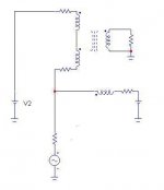
It appears topologically similar to the following
(apart from the use of CCS)
and it is a parafeed.
hint: substitute V2 with a capacitor.
Federico
Here is a sort of brute way of compensate for any DC in the transformer primary.
It appears topologically similar to the following
(apart from the use of CCS)
and it is a parafeed.
hint: substitute V2 with a capacitor.
Federico
Attachments
more efficient method to cancel DC current
How about connecting the power tube plate to the primary CT (and cathode to ground or whatever auto-bias resistor etc). The B+ connects to one of the primary end connections. The other primary end connection connects thru a current source to ground.
Advantages are that the current source only has to handle half the plate idle current, but will have to handle twice the voltage swing unfortunately. Also, this works with a CT primary without separated windings. Once could play around with the UL taps too, but this would just trade-off voltage for current in the source.
Don
Re: Re: Some little algebra
This happens with every common monolitic regulator IC?
Had you tried also simple Fet or BJT configuration ?
Are U telling us that LMxx IC current suppliyng a coil become a power oscillator without any possibility of loop compensation?dave slagle said:
... if you use a LM series as a current reg in your tertiary winding, you will get some nice high voltages. I was able to get 700V at around 70Khz across the primary simply by placing a LM338 as a current reg on a cancel winding.
This happens with every common monolitic regulator IC?
Had you tried also simple Fet or BJT configuration ?
Re: Re: Some little algebra
Yes, putting a permanent magnet IN the magnetic loop was my first idea too, but I was discouraged because to offset a significant portion of flux (say 1Tesla) one need big volume magnet (also with rare earth) and this means large gap, nothing different to a conventional gapped trafo.
I discarded also the idea to work below the knee of the demagnetization curve of magnets, where the permeability is higher, but this means also a permanent demgnetization when Idc is switched off.
I think that the only possibilities is to put permanent magnet outside the AC magnetic loop and to serach for a geometry that can offset the DC flux in the whole lenght of the ac magnetich path. Till now, several geometies I tried showed a part more o less huge with high flux, over the iron saturation limit.
Maybe this is the reason why PM dc flux compensation output transformer were never produced (they tried every strange idea, why not this?)
dave slagle said:
i still don't see this happening, but maybe i am missing something obvious. The only way i see it offsetting flux evenlu throughout the entire core is to place it in "series" with the core and this creates an airgap which eliminates the need for the cancelling.
now if some .001 inch N/S across the surface sheet magnet with enormous field strength could be found...
dave
Yes, putting a permanent magnet IN the magnetic loop was my first idea too, but I was discouraged because to offset a significant portion of flux (say 1Tesla) one need big volume magnet (also with rare earth) and this means large gap, nothing different to a conventional gapped trafo.
I discarded also the idea to work below the knee of the demagnetization curve of magnets, where the permeability is higher, but this means also a permanent demgnetization when Idc is switched off.
I think that the only possibilities is to put permanent magnet outside the AC magnetic loop and to serach for a geometry that can offset the DC flux in the whole lenght of the ac magnetich path. Till now, several geometies I tried showed a part more o less huge with high flux, over the iron saturation limit.
Maybe this is the reason why PM dc flux compensation output transformer were never produced (they tried every strange idea, why not this?)
Farber inductor version simulation
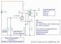
Just a little bit of playing with Spice. A little modification , combined Fig1 and Fig.3, one can obtain this circuit that give 8W at 2% THD with only 1 square cm section of iron and 1000 turns.
The 20H inductance works also as cathode resistor, and dissipated quite a lot of heat but can be large and there is no insulation (works at only 15V) to worry about.
I assumed an aux winding made of half the section of the main coil.
Not bad, for such a small iron.
Attachments
Re: Farber inductor version simulation
Tell me if I fail.
The cathode is AC grounded, so just the DC current flows trought the transfo and the choke wich voids shortening AC.
Due to the direction of windings, reducing the value of the cathode bypass capacitor sould introduce some POSITIVE feed back at the low of the spectrum. ... I bet
Could you simulate that "big boom boom" behaviour ?
<edit>
At second thought, the choke comes in parallel with the auxiliary winding and, as so, short it at low end, BUT the cap does exactly the inverse effect.
Perhaps a "certain" value of the cap could compensate for a "certain" value of the choke
Yves.
plovati said:Just a little bit of playing with Spice. A little modification , combined Fig1 and Fig.3, one can obtain this circuit that give 8W at 2% THD with only 1 square cm section of iron and 1000 turns.
The 20H inductance works also as cathode resistor, and dissipated quite a lot of heat but can be large and there is no insulation (works at only 15V) to worry about.
I assumed an aux winding made of half the section of the main coil.
Not bad, for such a small iron.
Tell me if I fail.
The cathode is AC grounded, so just the DC current flows trought the transfo and the choke wich voids shortening AC.
Due to the direction of windings, reducing the value of the cathode bypass capacitor sould introduce some POSITIVE feed back at the low of the spectrum. ... I bet
Could you simulate that "big boom boom" behaviour ?
<edit>
At second thought, the choke comes in parallel with the auxiliary winding and, as so, short it at low end, BUT the cap does exactly the inverse effect.
Perhaps a "certain" value of the cap could compensate for a "certain" value of the choke
Yves.
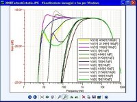
Yes, the value I posted for C and L are what after few trial give a good flat response.
Tweaking the value of C there is a bass boosting due to a combination of lack of AC grounding and the resonance of LC tank.
It is easy possible to go down to few Hz of power bandwidth but appears a bad ripple. Tweaking both L and C can be found some satisfatory response.
The question is: this arrangement can have some advantage over the common parafeed? Maybe less requirement of high Q inductor, less isolation for the same, low voltage cap.
Attachments
plovati said:Yes, the value I posted for C and L are what after few trial give a good flat response.
Tweaking the value of C there is a bass boosting due to a combination of lack of AC grounding and the resonance of LC tank.
It is easy possible to go down to few Hz of power bandwidth but appears a bad ripple. Tweaking both L and C can be found some satisfatory response.
The question is: this arrangement can have some advantage over the common parafeed? Maybe less requirement of high Q inductor, less isolation for the same, low voltage cap.
Great results indeed.
The dark side is that the total amount of iron (choke + tranny) will probably be the same that with the "gap" method.
Nevertheless the tweaking between L and C open a wide an intriging path, I like that !
Yves.
I just went back and looked at the 3 Farber diagrams and figures 1 and 2 are not working due to a cap across a winding.
Figure 3 is almost working. The problem with it is the resistance in the inductor will prevent equal DC currents from flowing thru both halves of the P-P transformer. This can be fixed by increasing the B+ voltage on the inductor somewhat above the B+ on the opposite xfmr end to equalize currents.
Another fix would be to move the tube's plate connection to an off center tap on the xfmr so that either circuit path has equalized ampere-turns thru the xfmr. (not equalized resistance pathes, must compute each resulting current and it's # of turns on xfmr)
Don
A simple elegant solution
If you run TWO SE amplifiers with inverted AC signal phase in one with respect to the other, then one can just put a DC bucking winding on each output transformer and connect them in series to a DC voltage supply. Adjust for correct DC current thru their winding resistance. No lossy current source necessary this way since the AC components cancel out.
Can use a couple of P-P center tapped transformers too by using a floating DC bucking supply between one end of each xfmr primary (B+ still goes to CTs and tube plates go to other primary ends). [ OR, can connect the primary ends together, without a floating bucking supply, and put the bucking DC supply between one CT and the other CT]
Wondering what to do with the other output now? Can connect the two output secondaries back together in series or parallel to drive a single speaker (get the AC phases correct).
Another solution suitable for a single toroid OT would be to wind the core lamination with a thin flexible permanent magnet sheet alongside the M6. This way you can put a lot of permanent magnet in without creating a huge air gap ( the large area around each turn effectively reduces the width of the gap).
Don
Re: Farber inductor version simulation
Chris Vryondies pointed this out to me a few years back as a way to use a dual primary TVC with 100% cancellation. I don't think he ever wired it up though.
dave
plovati said:Just a little bit of playing with Spice.
Chris Vryondies pointed this out to me a few years back as a way to use a dual primary TVC with 100% cancellation. I don't think he ever wired it up though.
dave
Re: A simple elegant solution
You're describing a PP! The connection of two different output trafos in a single load was described and made by Crowhurst in his Twin Coupled Amp, a sort of low cost Mc Intosh connection.
I don't think it works, the field is parallel to magneticg lenght, so just a little will be coupled with parallel lamination. Furthermore flexible plasticmagnet are weak and You lost lot of space in the core section, pumping up leakage inductance.
smoking-amp said:If you run TWO SE amplifiers with inverted AC signal phase in one with respect to the other, then one can just put a DC bucking winding on each output transformer and connect them in series to a DC voltage supply. Adjust for correct DC current thru their winding resistance. No lossy current source necessary this way since the AC components cancel out.
Can use a couple of P-P center tapped transformers too by using a floating DC bucking supply between one end of each xfmr primary (B+ still goes to CTs and tube plates go to other primary ends). [ OR, can connect the primary ends together, without a floating bucking supply, and put the bucking DC supply between one CT and the other CT]
Wondering what to do with the other output now? Can connect the two output secondaries back together in series or parallel to drive a single speaker (get the AC phases correct).
You're describing a PP! The connection of two different output trafos in a single load was described and made by Crowhurst in his Twin Coupled Amp, a sort of low cost Mc Intosh connection.
Another solution suitable for a single toroid OT would be to wind the core lamination with a thin flexible permanent magnet sheet alongside the M6. This way you can put a lot of permanent magnet in without creating a huge air gap ( the large area around each turn effectively reduces the width of the gap).
Don
I don't think it works, the field is parallel to magneticg lenght, so just a little will be coupled with parallel lamination. Furthermore flexible plasticmagnet are weak and You lost lot of space in the core section, pumping up leakage inductance.
Not the same!
Read the description more carefully, it's not the same as PP or Crowhurst's Twin Coupled amp. Draw the diagram as described.
Another clever alternative would be to make a third channel for a stereo system which would have -L-R signal on it. DC bucking coils in series around all three xfmrs then (the +L, the +R and the -L-R channels). Then could use the -L-R output as a center speaker channel (can just invert to +L+R by reversing secondary)
For the magnet version, the magnet has a field orthogonal to the sheet, not along its length. This field orientation is fine since the flux in the M6 sheet has to jump the gap from layer to layer once each turn. Since the sheet is distributed it does not need to be as strong as a single gap insertion. (The total flux produced by one whole turn of magnet sheet only has to buck the field in one lamination layer, this is probably a 1000x magnification of flux over a simple one gap insertion approach) Possibly can use flexible ferrite magnet filled rubber sheet as is used to make many refrigerator magnets (but might require a stronger magnet material, have to check the numbers), but must be thin.
Don
smoking-amp said:
For the magnet version, the magnet has a field orthogonal to the sheet, not along its length. This field orientation is fine since the flux in the M6 sheet has to jump the gap from layer to layer once each turn. Since the sheet is distributed it does not need to be as strong as a single gap insertion. (The total flux produced by one whole turn of magnet sheet only has to buck the field in one lamination layer, this is probably a 1000x magnification of flux over a simple one gap insertion approach) Possibly can use flexible ferrite magnet filled rubber sheet as is used to make many refrigerator magnets (but might require a stronger magnet material, have to check the numbers), but must be thin.
Don
I'm thinking to a toroidal core with some soft magnetic sheet paired to a rubber magnet with magnetization perpendiculrat to the sheet and win togheter. But in this case the field if perpendicular to the coil induced field so no cancellation at all. Maybe a schetck is better
- Status
- This old topic is closed. If you want to reopen this topic, contact a moderator using the "Report Post" button.
- Home
- Amplifiers
- Tubes / Valves
- DC compensated SE output transformer