Sure but the infinite current will be supplied by the infinite cap, in a pure math world.
In a more realistic engineering world, at frequency well below the LC resonant frequency, the coil does not appare anymore. If one is worried about the real winding that is shorted why does not worry also about the physical presence of the capacitor?
The experimentation has the last and definitive evidence, but I'm also trying to find out a clear logical a priori explanation. Tomorrow I plan to perform a simple test.
Re: More solutions for a DC free OPT
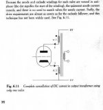
this hookup as SE will not work, since the AC will cancel along with the DC. Mac used it buy cross coupled Tube A plate to Tube B cathode which inverts one of the AC signals.
dave
Gluca said:Have a look to the schematics I found on M Jones' book. It is from an old Quad II and/or McIntosh amp. I personally don't like the idea that much ... it's just to add a reference on the subject.
Ciao
Gianluca
this hookup as SE will not work, since the AC will cancel along with the DC. Mac used it buy cross coupled Tube A plate to Tube B cathode which inverts one of the AC signals.
dave
test
a five minute test:
a junk box 115+115 / 15+15 V transformer.
applied 5V rms of variable frequency to one 115V winding by means of a 50ohm signal generator
the other isolated windings shows 5V, 156mV , 138mV
I shorted the 115V winding before left opened
results at 100Hz-500Hz unchanged
results at >1kHz somewhat funny: 100mV, 86mV, I suppose because the leakage capacitance distribution
I shorted all the winding except one 15V
signal on this coil 18mV at 100Hz
My conclusion is that till there is at least an open winding the flux is balanced by this one, when all the coils are shorted, efficiency drops down near zero.
What happens with resistive load (to be tested) I think is somewhat concerned the efficiency, not the general feature.
Re: More solutions for a DC free OPT
I never read Mr. Jones book, and after this post I'm wondering why this guy seems to be reputed one of the very top audio guru.
There is many tube books around available for free, like RDH4, lot better and not only 'cause are free!
Gluca said:Have a look to the schematics I found on M Jones' book. It is from an old Quad II and/or McIntosh amp. I personally don't like the idea that much ... it's just to add a reference on the subject.
Ciao
Gianluca
I never read Mr. Jones book, and after this post I'm wondering why this guy seems to be reputed one of the very top audio guru.
There is many tube books around available for free, like RDH4, lot better and not only 'cause are free!
Re: More solutions for a DC free OPT
Konnichiwa,
You will find that not all written im books (especially in the one you cite) agrees with reality.
Sayonara
Konnichiwa,
Gluca said:Have a look to the schematics I found on M Jones' book.
You will find that not all written im books (especially in the one you cite) agrees with reality.
Sayonara
Hi all
You are right about the whole line, Kuei Yang Wang.
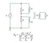
I calculated the resistance seen by a generator feeding a normal
PP trafo with two impedances as in attached figure.
It turns out to be a parallel impedance.
Yes, it is an ideal case with no winding res. and and ideal coupling.
Yes, it is not the topology of Farber patent since the 2nd coil
is differently wired but...
to obtain Farber circuit simply change in minus the sign to N2.
... and R in will go to zero due both to the short and to flux cancellation.
No compensation here. It does not work.
In the real world things may be different due to the coupling
factor. I read a paper on CHF (an Italian review) where
the Author (mr. Polisois if I remember) told that thing work
only under loose coupling condition. But I do not remember if
the compensation method proposed was exacly the Farber one.
Non conventional trafo simulation is a very difficult task.
remember that the coupling factor k is a (non symmetric) tensor quantity not a scalar one. Some simulators provide the way for only one value of k, others (e.g. Microcap) allow us
to use the matrix form ( but only symm.). No one
check for positivness (eigenvalues greater than zero) of the matrix. No one allow for different materials in the core
of the same coil.
So, some times it is not so simple to find the truth with simulations nor with maths and...
bye
Federico
think from extreme points, let us assume an ideal, infinite value capaictor. We have a shorted turn.
If I took a normal transformer and applied a shorted turn, I'd loose any output.
If I wind the cathode winding using thin wire I would still find that the DCR of winding appears in parallel with the load.
You are right about the whole line, Kuei Yang Wang.
I calculated the resistance seen by a generator feeding a normal
PP trafo with two impedances as in attached figure.
It turns out to be a parallel impedance.
Yes, it is an ideal case with no winding res. and and ideal coupling.
Yes, it is not the topology of Farber patent since the 2nd coil
is differently wired but...
to obtain Farber circuit simply change in minus the sign to N2.
... and R in will go to zero due both to the short and to flux cancellation.
No compensation here. It does not work.
In the real world things may be different due to the coupling
factor. I read a paper on CHF (an Italian review) where
the Author (mr. Polisois if I remember) told that thing work
only under loose coupling condition. But I do not remember if
the compensation method proposed was exacly the Farber one.
Non conventional trafo simulation is a very difficult task.
remember that the coupling factor k is a (non symmetric) tensor quantity not a scalar one. Some simulators provide the way for only one value of k, others (e.g. Microcap) allow us
to use the matrix form ( but only symm.). No one
check for positivness (eigenvalues greater than zero) of the matrix. No one allow for different materials in the core
of the same coil.
So, some times it is not so simple to find the truth with simulations nor with maths and...
The experimentation has the last and definitive evidence
bye
Federico
Attachments
fscarpa58 said:Hi all
I calculated the resistance seen by a generator feeding a normal
PP trafo with two impedances as in attached figure.
It turns out to be a parallel impedance.
See RDH4 chap. 5.1 pag 202. Well before the PC era this result was clear
fscarpa58 said:Yes, it is not the topology of Farber patent since the 2nd coil
is differently wired but...
to obtain Farber circuit simply change in minus the sign to N2.
... and R in will go to zero due both to the short and to flux cancellation.
I don't think so, to be a Farber topology You missed the cap. The key is that due to cap action the DC sees two (anti)series coils and the AC just one
fscarpa58 said:In the real world things may be different due to the coupling
factor. I read a paper on CHF (an Italian review) where
the Author (mr. Polisois if I remember) told that thing work
only under loose coupling condition. But I do not remember if
the compensation method proposed was exacly the Farber one.
I think is equivalent to Fg.2 topology. I cannot understand these loose coupling stuff. I one wants loose coupling, why do not wind two separate coil?
I think the point is, following RDH4 theory, that when You have two secondaries, signal power from the primaries shares between them according to maximum power transfer theorem. This means that power should flow in the winding that has impendance closer to source impedance.
]Originally posted by fscarpa58
Non conventional trafo simulation is a very difficult task.
remember that the coupling factor k is a (non symmetric) tensor quantity not a scalar one. Some simulators provide the way for only one value of k, others (e.g. Microcap) allow us
to use the matrix form ( but only symm.). No one
check for positivness (eigenvalues greater than zero) of the matrix. No one allow for different materials in the core
of the same coil.
This is too complicated for me. Are you speaking about phase relationship beetween the coils?
Re: test
IMHO, you just measured the internal impedance of your sig gen and various kinds of losses in the tranny !
Would you dare to tie the primary to a 115V main power line ?
(Have some spare fuses at hand)
Yves.
plovati said:a five minute test:
a junk box 115+115 / 15+15 V transformer.
applied 5V rms of variable frequency to one 115V winding by means of a 50ohm signal generator
the other isolated windings shows 5V, 156mV , 138mV
I shorted the 115V winding before left opened
results at 100Hz-500Hz unchanged
results at >1kHz somewhat funny: 100mV, 86mV, I suppose because the leakage capacitance distribution
I shorted all the winding except one 15V
signal on this coil 18mV at 100Hz
My conclusion is that till there is at least an open winding the flux is balanced by this one, when all the coils are shorted, efficiency drops down near zero.
What happens with resistive load (to be tested) I think is somewhat concerned the efficiency, not the general feature.
IMHO, you just measured the internal impedance of your sig gen and various kinds of losses in the tranny !
Would you dare to tie the primary to a 115V main power line ?
(Have some spare fuses at hand)
Yves.
fscarpa58 said:
In the real world things may be different due to the coupling
factor. I read a paper on CHF (an Italian review) where
the Author (mr. Polisois if I remember) told that thing work
only under loose coupling condition. But I do not remember if
the compensation method proposed was exacly the Farber one.
But.... why?
Any cancelation winding will appear essentially as a secondary winding to the tube(s.) Hence, whatever impedance presented to that winding will appear essentially in parallel with the intended load (the speaker.) The only right way to deal with that is to make the impedance at the cancel winding very high so that it doesn't affect the audio circuit.
Putting a big capacitor across the winding as Farber did is just plain stupid. Really, it's just stupid.
Trying to hide a low impedance with deliberately poor coupling is treating the symptom not the disease and can only work partially anyway; there are practical limits to how bad you can make the coupling between two windings on the same core. The likelyhood of it resulting in a really good sounding system is pretty low, I would guess.
I'll say it again: the only right way to make a cancel winding work is to feed it with a very high impedance; a CCS, or at least a large choke in series.
-- Dave
As I warned I am a bit late in catching up: I started participating in this discussion because there was some debate about the use of compensating current windings and their effects on performance. There were interesting points with some back and forth but at last one individual could not tolerate different views about PP vs. SE.
Yet when I dare to mention that there is a "SET sound" you reply:
So it would appear that you sometimes use "tricks" to make your amplifiers sound like something you then claim doesn't exsist.
Actually my exact words were: "At least part of the explanation..." A long way from claiming one main explanation.
Local feedback is a term us electrical engineers use to seperate it from multi stage or global feedback and also to seperate it from degeneration it is a kind of shorthand and we all (even you I think) know what is meant.
I originally said:
Driver manufacturers do not intentionally make their drivers un-efficient but they do strive for flat and low distortion. This usually results in a driver of 85 to 90 dBSPL.
Your reply is quite stunning in it's breadth if not so much in wisdom. There are drivers that are the best that can be made at any number of given price points. People such as Ejvind and Per Skaaning have devoted a lifetime to developing drivers that are conventional and are used in the most reknown speaker systems available at any price but according to you wrongly designed.
Amazingly enough the replies gradually become a rant instead of a debate closing with an I'm right youre wrong and there is nothing left to say.
There is in fact room for debate, all is not understood, and one answer is not right for everyone or all situations.
I have no interest in worshipping Kuei Yang Wang at his church of all knowledge. Perhaps others might wish to ask for an address and a list of sermons.
originally posted by Kuei Yang Wang
One of my tricks to make my Push-Pull amplifiers sound a lot more "SE"
Yet when I dare to mention that there is a "SET sound" you reply:
originally posted by Kuei Yang Wang
Have you HEARD this signature sound?
(BTW, my experience is that there is no such thing - SE Amp's using drastically different topologies sound dramatically different, much more so than traditional PP Valve Amps and/or Solid State Amplifiers by a LARGE margin)
So it would appear that you sometimes use "tricks" to make your amplifiers sound like something you then claim doesn't exsist.
originally posted by Kuei Yang Wang
Forgive me, but was it not you ho generalised and claimed that there was one main explanation?
Actually my exact words were: "At least part of the explanation..." A long way from claiming one main explanation.
originally posted by Kuei Yang Wang
Sorry, but there is no such thing as "local" feedback,
Local feedback is a term us electrical engineers use to seperate it from multi stage or global feedback and also to seperate it from degeneration it is a kind of shorthand and we all (even you I think) know what is meant.
I originally said:
Driver manufacturers do not intentionally make their drivers un-efficient but they do strive for flat and low distortion. This usually results in a driver of 85 to 90 dBSPL.
originally posted by Kuei Yang Wang
Sorry, that is simply and demonstrably wrong.
Driver manufactuers that produce the kind of drivers you mention, by the very basic laws of physics make drivers subject to comparably high levels of distortion and compression. They continue to do so as it provides profit, quality is actually immaterial in the context.
Your reply is quite stunning in it's breadth if not so much in wisdom. There are drivers that are the best that can be made at any number of given price points. People such as Ejvind and Per Skaaning have devoted a lifetime to developing drivers that are conventional and are used in the most reknown speaker systems available at any price but according to you wrongly designed.
Amazingly enough the replies gradually become a rant instead of a debate closing with an I'm right youre wrong and there is nothing left to say.
There is in fact room for debate, all is not understood, and one answer is not right for everyone or all situations.
I have no interest in worshipping Kuei Yang Wang at his church of all knowledge. Perhaps others might wish to ask for an address and a list of sermons.
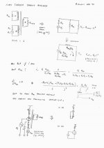
Some little algebra
So, despite Yves that want me dead playing with 115V,
I tried to play with more safe signal generator and I'm convinced that this method works, in the sense that a signal came out from the secondary and that the DC flux is cancelled.
It is, as many of the things in the real life, a question of balance between contrasting factor and in this case the key parameter is the load power transfer efficiency.
I made some little calculus reported below that confirm what Dave said.
The current sink supplied aux winding may be a good solution, achieving the same efficiency of the conventional method but without DC flux. Putting the aux winding in cathode branch is possible to use for most of the tube a simple low voltage IC like LM317. I like this variation, what is Yours opinion?
But I'm still searching for a permanent magnetic field counterbalances the DC flux, so no extra winding required.
Attachments
Keep you alive !
Hi !
No, please stay alive !
Even if I'm still not convinced I refuse to kill anyone just cos our ideas don't match
Tests with sig gen are of course safer.
Yves.
Hi !
So, despite Yves that want me dead playing with 115V,
No, please stay alive !
Even if I'm still not convinced I refuse to kill anyone just cos our ideas don't match
Tests with sig gen are of course safer.
Yves.
hi Piergiorgio, all
trafo reduces its (of the trafo) input impedance to zero (under the specified hypotesis).
take another look at the image.
in place of Z1 put the cap
in place of Z2 put nothing (infinity res)
and you 'll have the Farber stuff.
Still not, you have to rewire the second coil as in
Farber patent and things go worst (N2 became -N2).
Clear and correct!
Federico
PC era?? and then? I did it with pen and paper, where is the problem. The result shows that a short on one coil of a PPWell before the PC era this result was clear
trafo reduces its (of the trafo) input impedance to zero (under the specified hypotesis).
I don't think so, to be a Farber topology You missed the cap.
take another look at the image.
in place of Z1 put the cap
in place of Z2 put nothing (infinity res)
and you 'll have the Farber stuff.
Still not, you have to rewire the second coil as in
Farber patent and things go worst (N2 became -N2).
Any cancelation winding will appear essentially as a secondary winding to the tube(s.) Hence, whatever impedance presented to that winding will appear essentially in parallel with the intended load (the speaker.) The only right way to deal with that is to make the impedance at the cancel winding very high so that it doesn't affect the audio circuit.
Putting a big capacitor across the winding as Farber did is just plain stupid. Really, it's just stupid.
Clear and correct!
Federico
A second look !
Wonder if B+ is an Hiz Voltage source.
Perhaps, just the coil from fig.3 missing ?
Typo
Yves.
fscarpa58 said:hi,
I agree that circuit of fig.3 works.
but I feel cir of fig.2 will never work.
bye
Federico
Wonder if B+ is an Hiz Voltage source.
Perhaps, just the coil from fig.3 missing ?
Typo
Yves.
Hi Federico and Yves,
I'm still alive and I agree (now) with your wiev of the shorting cap.
An ad hoc design can be made with thinner wire and high DC resistance for the aux wire in order not to loose much power or better the suggestion of Dave of a CCS, electrical equivalent to the inductor topology. In this latter case the only advantage of Farber over the parafeed is the minor inductor current and no coupling cap.
Sorry Federico I misunderstood yours picture, and nothing against PC, just a little of envoy for people with those skills.
Thanks for yours contributions, they leads me to a clearer picture.
Thorsten said:
<<Agreed up to point. Thinking about the various methodes has gotten me to a design (which for now will remain outside the public domain as I will investigate patenting it) that offers a much superior methode.... ;-)>>
Any clues of his improvements?
Konnichiwa,
Poor choice of phrase, perhaps would been "I can make a PP Amplifer sound very much alike to my SE Amplifiers, WITHOUT adding large amounts of even harmonics.
I use "tricks" to make them sound how I want them to. In order to do so ome must understand why things sound the way they do, at least in large outlines, if not in minute detail.
And I reply, not even in part. The assertation that the amounts of even harmonics present in an SE Amp are what makes them sound "sweet(er)" is false and remains false, be it as partial or as complete explanation.
I give up.
Even Ejvind and Per Skaaning have to work within the bounds of physics. That means their drivers will behave in certain ways, which can be predicted by a number of factors with good accuracy.
Low Efficiency Drivers are wrongly designed if low distortion and low compression are considered a "good thing", no matter who designs them. If not the "high distortion" of an SE Amp cannot be a "bad thing".
BTW, Skaanings company makes Drivers that are low compression and low distortion, they also are high efficiency as it so happens....
I agree that all is not fully understood, however in the area in which I have attempted to correct you untrue statements we have a number of facts that stand in direct contradiction to you statements making them untrue, therefore indeed, there is no debate possible.
We may debate what sounds good to you, subjectively and to me and do so endlessly (as we clearly prefer very different types of sound for our listening), but facts CANNOT be debated, they merely are.
Sayonara
hermanv said:Yet when I dare to mention that there is a "SET sound" you reply
Poor choice of phrase, perhaps would been "I can make a PP Amplifer sound very much alike to my SE Amplifiers, WITHOUT adding large amounts of even harmonics.
hermanv said:So it would appear that you sometimes use "tricks" to make your amplifiers sound like something you then claim doesn't exsist.
I use "tricks" to make them sound how I want them to. In order to do so ome must understand why things sound the way they do, at least in large outlines, if not in minute detail.
hermanv said:Actually my exact words were: "At least part of the explanation..."
And I reply, not even in part. The assertation that the amounts of even harmonics present in an SE Amp are what makes them sound "sweet(er)" is false and remains false, be it as partial or as complete explanation.
hermanv said:Local feedback is a term us electrical engineers use to seperate it from multi stage or global feedback and also to seperate it from degeneration it is a kind of shorthand and we all (even you I think) know what is meant.
I give up.
hermanv said:Your reply is quite stunning in it's breadth if not so much in wisdom. There are drivers that are the best that can be made at any number of given price points. People such as Ejvind and Per Skaaning have devoted a lifetime to developing drivers that are conventional and are used in the most reknown speaker systems available at any price but according to you wrongly designed.
Even Ejvind and Per Skaaning have to work within the bounds of physics. That means their drivers will behave in certain ways, which can be predicted by a number of factors with good accuracy.
Low Efficiency Drivers are wrongly designed if low distortion and low compression are considered a "good thing", no matter who designs them. If not the "high distortion" of an SE Amp cannot be a "bad thing".
BTW, Skaanings company makes Drivers that are low compression and low distortion, they also are high efficiency as it so happens....
hermanv said:There is in fact room for debate, all is not understood, and one answer is not right for everyone or all situations.
I agree that all is not fully understood, however in the area in which I have attempted to correct you untrue statements we have a number of facts that stand in direct contradiction to you statements making them untrue, therefore indeed, there is no debate possible.
We may debate what sounds good to you, subjectively and to me and do so endlessly (as we clearly prefer very different types of sound for our listening), but facts CANNOT be debated, they merely are.
Sayonara
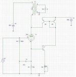
Hi all!
Here is a sort of brute way of compensate for any DC in the transformer primary. One nice feature is also that one can off-set the core from zero mA to what ever value you like using the trimmer. It is easy to try if you have the ability to add some B+. Another way would be to add an inductance between the anode and the current mirror and maybe also an AC ground at the current mirror output. If that is done you only need to add a few volts above B+. I have not tried this since i find PP so much better than any SE i have ever heard, SE is a bit to romantic for my taste.
BR,
Anders
Attachments
- Status
- This old topic is closed. If you want to reopen this topic, contact a moderator using the "Report Post" button.
- Home
- Amplifiers
- Tubes / Valves
- DC compensated SE output transformer