WOW, saw this thread just now right before I was ready to pull the trigger to replace my NINE year old Rythmik Audio plate amps with a pair of the Dayton SA250 amps. Geez, seems these Daytons fail like crazy after reading all the complaints on Amazon and here. Had no clue I've had great luck with the older version Dayton Titanic woofers from the former Dayton company still going strong... but what gives with these Dayton plate amps.
Did Parts Express ever get this straightened out or these things still junk after 1-2 years?
Is there any brand new 250/300 watt plate amp worth buying these days?
Did Parts Express ever get this straightened out or these things still junk after 1-2 years?
Is there any brand new 250/300 watt plate amp worth buying these days?
Hello everyone :
I have bought the Dayton SPA250.
I do not want to use bass boot, I wanted to test its operation but applying a small lateral pressure, either left or right, it does not move ......
It seems that it has a lock, you have to lift it first and then move? This would be impossible to realize for that small hole, would have to remove before the plastic shell that protects the whole amplifier.
I enclose my correspondence with Dayton:
Question
" I have the following questions about the bass switch.
1) I have tried to slide the visible part (see photo) gently and does not move. I'm afraid of hurting something if I exert too much pressure. Can you please inform me how is the correct method ?
2) The position of the switch (as I received it from the factory) corresponds to Off or to On ? "
Answer
" It is a little micro switch that is what you typically find on PCB's, so it is not very robust. But it should be set to off all the way to the left. And if you want it on then it slides to the right."
Can you help me, please ? I just need to know if in the position you see in the photo is disabled, then I would leave it like this ....
Thanks since now")
I have bought the Dayton SPA250.
I do not want to use bass boot, I wanted to test its operation but applying a small lateral pressure, either left or right, it does not move ......
It seems that it has a lock, you have to lift it first and then move? This would be impossible to realize for that small hole, would have to remove before the plastic shell that protects the whole amplifier.
I enclose my correspondence with Dayton:
Question
" I have the following questions about the bass switch.
1) I have tried to slide the visible part (see photo) gently and does not move. I'm afraid of hurting something if I exert too much pressure. Can you please inform me how is the correct method ?
2) The position of the switch (as I received it from the factory) corresponds to Off or to On ? "
Answer
" It is a little micro switch that is what you typically find on PCB's, so it is not very robust. But it should be set to off all the way to the left. And if you want it on then it slides to the right."
Can you help me, please ? I just need to know if in the position you see in the photo is disabled, then I would leave it like this ....
Thanks since now
Attachments

low gain SA240
I had the problem of near zero gain for two of the SA240 's . They have spend most of their life on standby. In both amps I tracked the problem down to failed C10 100mmf cap which is located in the feedback network. After replacing the caps I measured -5 mv across the cap when in standby and +50 mv when fully on. Can the negative DC bias over years breakdown the aluminum electrolytic cap ? Would a bipolar cap be a better choice ?
I had the problem of near zero gain for two of the SA240 's . They have spend most of their life on standby. In both amps I tracked the problem down to failed C10 100mmf cap which is located in the feedback network. After replacing the caps I measured -5 mv across the cap when in standby and +50 mv when fully on. Can the negative DC bias over years breakdown the aluminum electrolytic cap ? Would a bipolar cap be a better choice ?
Hi Guys,
My 6 year-old SA240 amp fried a month ago i tried to replace the transistors but with no success, the PCB is of low quality, so i replaced it with an Infinity TSS-1200 for $120 but it won't match with my Bose 301 fronts. My SA240 cost $98 + $100 shipping at that time (from PE to Philippines).
So i planned to reuse the Transformer, Heatsink and the Preamp of my old SA240 with this amp from Aliexpress (attached).
A3-BASS 300W high-power subwoofer amplifier board can do single-channel full frequency
55VX2 300W
33VX2 140W
28VX2 90W
24VX2 70W
18VX2 40W
My question is can i just use the SIN, +18V and Ground of the preamp without using the other 3 jumpers (Standby, Protection and Temperature)?
Thank you in advance!
Hi -- I know this is an old thread, but there don't seem to be many out there about repairing the SA240. Mine makes a 60Hz hum when I turn the Gain knob up past about 60%... and it gets louder the higher you turn the gain. And this happens even with no signal input at all. I also noticed burnt RS1 and RS2 and the trace on them has separated from the PCB.
Would those resistors be the cause of the hum? I don't care about the soft limit circuit, so I can just remove those resistors completely?
I like your idea of repurposing some parts with a new amp from Aliexpress... but I need an identical plate size to fit into the back of my DIY sub enclosure.
There are funny things in many companies. Dayton's argument for refusing to supply me with the SPA250 circuitry was the same as that of all audio manufacturers:
"The diagram is protected by intellectual property laws" A friend told me that something similar happened to him with the circuit of a Tannoy xover ....
With patience and time available, I could decipher this "Egyptian hieroglyphs" myself, Dayton thinks the Chinese don't? Yes surely they have already done it!
Couldn't Dayton do himself and do the "victims" a favor and release the diagram now that this model is out of production?
" I have the following questions about the bass switch.
1) I have tried to slide the visible part (see photo) gently and does not move. I'm afraid of hurting something if I exert too much pressure. Can you please inform me how is the correct method ?
2) The position of the switch (as I received it from the factory) corresponds to Off or to On ? "
Answer
" It is a little micro switch that is what you typically find on PCB's, so it is not very robust. But it should be set to off all the way to the left. And if you want it on then it slides to the right."
See post 43
The problem was that the black sliding knob of the microswitch could not be seen with the naked eye as the hole-peephole was moved from the correct point, the adhesive poster is correct.
And yes, my vision is not the same as it was at 20 years old ...
Last edited:
There are funny things in many companies. Dayton's argument for refusing to supply me with the SPA250 circuitry was the same as that of all audio manufacturers:
"The diagram is protected by intellectual property laws" A friend told me that something similar happened to him with the circuit of a Tannoy xover ....
With patience and time available, I could decipher this "Egyptian hieroglyphs" myself, Dayton thinks the Chinese don't? Yes surely they have already done it!
Couldn't Dayton do himself and do the "victims" a favor and release the diagram now that this model is out of production?
I believe there is a schematic available on one of the posts here as an attachment. Let me know if you don't find it -- I have a copy.
I am still wondering about the 60Hz hum though. I'd like to keep using this amp if I can, and if all it takes is simply removing those two burnt 1/2W resistors.
Hello. Reviving an old thread here, but i'm getting so-so results with the mod in this thread; ive replaced the U2 with a 10k resistor and removed the burnt rs1 and rs2, but i need to put the gain at the very max to get sound from the sub. Anything special i can do to fix this, use a different value resistor or something else ? thanks for any input.
I am just reading this thread, I have a brand new out of box that pops every so often, its a 7hz 25vrms oscillation that comes and goes. Seems to happen more when running amp above and average of 4-6vrms output. I am just getting into why is it doing this and will report back later with findings/fix.
Going by a pervious posters comments about the power switch issue (my issue closely related his issue), I got looking into this to start. What I found was this "popping noise" issue on this brand new amp was indeed originating in the "preamp board". "scoping & reading voltage showed nothing, but I did notice in that the issue seem to get less as the unit played longer. (heat??) I did check caps, (not that there should be issue with NIB amp but built in approx. 2019 by date codes), I moved IC's to different locations to see if problem would move / change. What I discovered in that is if I tapped on board around U2 I could get it to act up. So I resoldered the entire preamp board with decent leaded solder and it has not acted up since. Not scientific troubleshooting but issue seems to be resolved so I'll take the win! Good thing to cause Dayton will NOT respond to my warranty claim emails, which I've read else where they terrible for warranty claims. 5 Year warranty which they will never honor / cheap Chinese solder / bad wave soldering leaves me with this advice, stay away from DAYTON buy something else where possible
Is it the schematic for the NHT-SW10? Or is there one specific to the Dayton SPA250?I believe there is a schematic available on one of the posts here as an attachment. Let me know if you don't find it -- I have a copy.
I am still wondering about the 60Hz hum though. I'd like to keep using this amp if I can, and if all it takes is simply removing those two burnt 1/2W resistors.
I have an essentially new, but years old SPA250 that I would like to revive. Amp was given to me NIB, but after sitting on a shelf for years. I built a sub based on a Paradigm 12" sub. After maybe 10 hours playing time, I got curious about that bass boost switch. I went through the nearly blind access hole with a pencil, eraser end down, and tried to move the switch. It fell apart instead of sliding. Now, when the amp is powered on, it immediately blows the replaceable fuse. Instantly, even with no load or input signal. Acts like a dead short. The switch is no longer functioning so I would think the circuit is simply open, not shorted. I can find no evidence of excess heat on any components or the circuit boards. Could that broken switch cause a short? Can I just remove it and put in a couple tiny jumpers to complete the circuit?See post 43
The problem was that the black sliding knob of the microswitch could not be seen with the naked eye as the hole-peephole was moved from the correct point, the adhesive poster is correct.
And yes, my vision is not the same as it was at 20 years old ...
Attachments
Once again, the problem is not having circuits. But I see that you have done a careful survey, there will be no problem in switching in a fixed way with jumpers and extracting that micro switch of terrible quality and enormous fragility. Choose ON or Off, you decide.
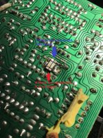
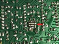
I see a track accidentally cut (under the red arrow photo 9967) maybe that's why the fuse is blown. And there are leftover solders that should be removed, it seems that they can short circuit nearby tracks.... PCB circuits require very good eyesight and hand, I work with a watchmaker's loupe.
I see a track accidentally cut (under the red arrow photo 9967) maybe that's why the fuse is blown. And there are leftover solders that should be removed, it seems that they can short circuit nearby tracks.... PCB circuits require very good eyesight and hand, I work with a watchmaker's loupe.
Attachments

SPA250 Auto On news:
Automatic power on when the circuit detects an audio signal works perfectly....... ONLY IN LOW LEVEL MODE!
I have decided to sell this unit, since I don't use it, and it occurred to me to try it with a cable in the RCA input, and touch it with my finger to inject a signal. It worked fine repeatedly.
It doesn't work if we take a signal from the speaker output...wow, it doesn't say so in the manual...anyone has forgotten, right?
But I want to be fair to Dayton, it is evident that the person in charge of the technical inquiries by mail was not aware of this. Dayton is a multi-product company, and perhaps for this reason, it lacked information....
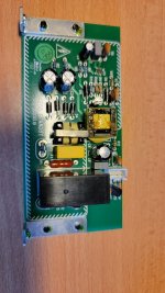
My ~4 years old SPA250 was not turning on and clicking of the power relay can be heard. I was about to write off this unit given all the horrible stories I read here and elsewhere, but I got bored one weekend and opened it up. Armed with the schematics of the amplifier section of a similar model I found on the net, I planned to measure power supply rails, but I never got that far. Turns out the power control board (to which I have no schematics) that detect audio and turn on the amp was attempting to turn on the amp and clicking the power relay. This board (photo attached) has a DC power supply that supply standby voltage (12V) to the preamp board. This power supply has a puffed capacitor "C8" (in the photo, it is the round black can with silver top left of the 3 pin molex connector). Replacing this cap with a salvaged cap (16V 470uF or larger) from a broken PC power supply repaired the unit. One would not expect electrolytic capacitors to fail so early, but I suspect Parts Express had these units on the shelf for years before selling them.
Attachments
I pulled one of these out that had been stored for about 6 years the other day. I plugged it in and got a bunch of big thumps /vibrations without any signal connected. The driver was actually fully extended. When I switched the reverse polarity switch it would suck the driver fully in and make the same aweful vibration. I pulled the amp apart and found similar burnt resistors at RS1, RS2, and R40, R41 like many found here. I also found a blown up resistor at R12. I replaced R12, R40, and R41, then disabled the soft limit circuit with a 10K resistor. I put it all back together and now when I power it up I get a hum. It will still play, but the hum makes it almost useless. It hums plugged in without any signal plugged it. In fact it hums much louder when switched off. I don’t see anymore burnt components, does anyone have a hood next step to troubleshoot?
- Home
- Loudspeakers
- Subwoofers
- Dayton SPA250 Plate Amplifier repair help