MikeB said:
Have you ever heard uncontrolled bass on big vented boxes ? uaergh !
LF ringing [LF 'domination' if your room rings at the same frequency than the speaker], but small drivers and/or small enclosures usually benefit from this
Hi, Mike,
 You are right. I forgot that these "nice sounding amps" are VERY PICKY to speaker. It has tobe matched with the speaker. Cannot play those amp with any speaker , especially the "heavy" one. Usually prefer the high-efficiency type, since their rating is very small. But if it found its match, they do sound nice.
The wife sings a song, and Mr Wilson playback the same song from the CD in the sound room. (That's why that speaker is very expensive. You've got to invite Mr.Wilson and his wife to sing at your house)
Then the guy move to a new house, and change the amp for powering the WAMM. In the new setting, he REFUSES to use the EQ supplied with the WAMM. He said, the EQ distorted his sound system. The sound becomes all mids and trebles, and it is coming from a speaker system with 15" woofer!!!
This attitude comes from ones who calls themself AUDIOPHILES. These people usually stubborn, they rather spend $$$$ on cables than to buy a good EQ.
You are right. I forgot that these "nice sounding amps" are VERY PICKY to speaker. It has tobe matched with the speaker. Cannot play those amp with any speaker , especially the "heavy" one. Usually prefer the high-efficiency type, since their rating is very small. But if it found its match, they do sound nice. This remind me of a (funny, I think) story. Once there is a guy in my city bought a very expensive speaker (Wilson Audio WAMM). Mr. Wilson and his wife comes to his house, tuning the boxes (they can slided back and forth), setting the EQ (If you buy one of these, it is equipped with a 30band EQ from Mr.Wilson).I prefer to use an equalizer and a 'linear system' instead
The wife sings a song, and Mr Wilson playback the same song from the CD in the sound room. (That's why that speaker is very expensive. You've got to invite Mr.Wilson and his wife to sing at your house
)Then the guy move to a new house, and change the amp for powering the WAMM. In the new setting, he REFUSES to use the EQ supplied with the WAMM. He said, the EQ distorted his sound system. The sound becomes all mids and trebles, and it is coming from a speaker system with 15" woofer!!!
This attitude comes from ones who calls themself AUDIOPHILES. These people usually stubborn, they rather spend $$$$ on cables than to buy a good EQ.
You get the same effect by setting a resistor in series with the
woofer. There are formulas how a resistor change the QTS-value
of a speaker. But, typically low QTS-values are preferred as they
reproduce more exact, so using a "weak" amp to get higher QTS
seems a bit paradox to me.
woofer. There are formulas how a resistor change the QTS-value
of a speaker. But, typically low QTS-values are preferred as they
reproduce more exact, so using a "weak" amp to get higher QTS
seems a bit paradox to me.
Ugh!
According to my ears no system really gets benefits from LF ringing of the room. ...OK, you can get the bass boosted to a louder level by this, but I never heard a set up, which did really 'benefit' from this. Unconvinient, annoying sound !!
Let's assume some normal small room.
Floor to top about 2.4m: ==> 71Hz
Left to right about 3m: ==> 57 Hz
Back to front about 4,5m ==> 38 Hz
All three main resonances of the room are nicely somewhere in the typical bass frequencies of music.
The damping of normal rooms shows poor Q for its main resonances, typically Q=5 ... Q=15 ! ...resulting in that inconvinient booming bass.
I love bass, but I dislike booming.
Furtheron many people blame the booming of their set up to a poor
damping factor of the amp. Usually this is not the real reason. Even a poor damping factor of 10 does not dominate the resulting Q of your speaker (Qbox may move from 0.7 to 0.9 - who cares....).
Most systems suffer mainly from the undamped room resonances in combination with an unfortunate position of the speaker or sub woofer.
A very simple method to evaluate if you are in trouble with LF ringing of the room is to listen in different positions. If there are positions which give significantly more bass (often close to the walls, floor and corners) and some positions with poor bass, then you might try another geometric set up....
Fighting the booming, while still providing a satisfying fundamental bass can easily take me half a year of experimentation....
Changing position of the speakers, the subwoofer, the furniture, may be some dampers in a corner...
Hi, Mike,
You nail it sharp. You said that THD number based on single sine wave measurement is meaningless for knowing the sound. PMA is developing measurement method in other thread that uses not single sinewave, but multiple sine wave in a certain composition. And it reveals something that single wave measurement hides.
I think your idea can lead to a single measurement method (brother of THD) that can judge if one amp sounds good or bad (a measurement number that can measure the sound quality of amp reproduction). What is your next idea of this?
You nail it sharp.
You said that THD number based on single sine wave measurement is meaningless for knowing the sound. PMA is developing measurement method in other thread that uses not single sinewave, but multiple sine wave in a certain composition. And it reveals something that single wave measurement hides. I think your idea can lead to a single measurement method (brother of THD) that can judge if one amp sounds good or bad (a measurement number that can measure the sound quality of amp reproduction). What is your next idea of this?
ChocoHolic said:Ugh!
According to my ears no system really gets benefits from LF ringing of the room. ...OK, you can get the bass boosted to a louder level by this, but I never heard a set up, which did really 'benefit' from this. Unconvinient, annoying sound !!
Let's assume some normal small room.
Floor to top about 2.4m: ==> 71Hz
Left to right about 3m: ==> 57 Hz
Back to front about 4,5m ==> 38 Hz
All three main resonances of the room are nicely somewhere in the typical bass frequencies of music.
The damping of normal rooms shows poor Q for its main resonances, typically Q=5 ... Q=15 ! ...resulting in that inconvinient booming bass.
I love bass, but I dislike booming.
Furtheron many people blame the booming of their set up to a poor
damping factor of the amp. Usually this is not the real reason. Even a poor damping factor of 10 does not dominate the resulting Q of your speaker (Qbox may move from 0.7 to 0.9 - who cares....).
Most systems suffer mainly from the undamped room resonances in combination with an unfortunate position of the speaker or sub woofer.
A very simple method to evaluate if you are in trouble with LF ringing of the room is to listen in different positions. If there are positions which give significantly more bass (often close to the walls, floor and corners) and some positions with poor bass, then you might try another geometric set up....
Fighting the booming, while still providing a satisfying fundamental bass can easily take me half a year of experimentation....
Changing position of the speakers, the subwoofer, the furniture, may be some dampers in a corner...
Good post, give the man a cigar (or some chocolate)
Such is the reason most mastering facilities have minimum
12 foot ceiling and usually angled with extensive room
treatment.
Terry
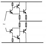
the main idea is like thisthanh said:can anyone know about "triple output"? it's not triple darington
Attachments
sss said:
the main idea is like this
Look like a better idea, and I imagine would have better voltage swing than darlington.
Would this be a hard arrangement to bias?
EWorkshop1708 said:Would this be a hard arrangement to bias?
its easy to bias but oscilation will be a problem . i saw few designs with this arrengement .if u will be able to stabilize it then the distortion figures will be much better then tripple darlington
Doug Self classified the ClassB output stage distortion into 3.
1. LSN (Large Signal Nonlinearities) occurs with BJT because they cannot maintain HFE with large output have to be delivered to the speakers. HFE fluctuation---distortion.
2. Crossover distortion. Happening when NPN ends working and giving task to PNP for reproducing signal.
3. Turn-off distortion. He said this distortion is helped a little in EF double follower, but cannot be eliminated in CFP output stage.
No.1 and 2. I could imagine. But I do not understand no.3. What is Turn-off distortion? Transistors have tobe turned off fast enough so it dont give distortion? Isn't that in class AB we try to have no single transistor tuned off at all? How it cannot be eliminated in CFP output stage?
Turn off distortion occurs because when a transistor is switched on fairly hard it kind of sticks on a bit even when drive is removed. The way to minimuse the effect is to ensure that the base can be pulled down hard and quickly (i.e. reverse biased) to suck out the excess charge.
You cannot do this with CFP because it's impossible to reverse bias the output device. To achieve this with EF output you need to use Self's EF Type II scheme, normal Darlington connection will not achieve the required reverse bias.
You cannot do this with CFP because it's impossible to reverse bias the output device. To achieve this with EF output you need to use Self's EF Type II scheme, normal Darlington connection will not achieve the required reverse bias.
Hi, Richie00boy,
Thanks for the explenation. So if I say it in simple words, the transistor is not turned off when it should have turned off because it still has charge in the base?
In Dougself EF typeII he put small C like 100nF between emitor-emitor of the drivers, parrarel to the R. Is this C causing the charge suckout? What if I not put this C parrarel with R, this EF II will not be able to reverse bias?
Back to CFP. Sajti suggest to put small C 10nF between output transistors. He said this is for advoiding cross conduction. I wonder if this can also reduce turnoff distortion?
QSC uses CFP in all their power amp. The CFP driver resistor is quite small, like 22ohm. Will this be able to help reducing turnoff distortion too? (Usually like in Douglself book, he suggested 100ohm)
lumanauw said:So if I say it in simple words, the transistor is not turned off when it should have turned off because it still has charge in the base?
Yes.
lumanauw said:In Dougself EF typeII he put small C like 100nF between emitor-emitor of the drivers, parrarel to the R. Is this C causing the charge suckout? What if I not put this C parrarel with R, this EF II will not be able to reverse bias?
The R alone is sufficient to effect reverse bias, the C just helps speed it up.
lumanauw said:Back to CFP. Sajti suggest to put small C 10nF between output transistors. He said this is for advoiding cross conduction. I wonder if this can also reduce turnoff distortion?
I'm not sure what you mean by 'between'. Which terminals? Cross conduction is a result of the device not switching off as quickly as the opposite member in the output stage is switching on. Basically turn off distortion means the essentially same thing.
lumanauw said:QSC uses CFP in all their power amp. The CFP driver resistor is quite small, like 22ohm. Will this be able to help reducing turnoff distortion too? (Usually like in Douglself book, he suggested 100ohm)
The lower the resistor value then the more current it can flow at a given voltage, so yes, it should speed up turn off.
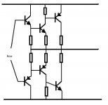
the main idea is like this
Sorry to be resurrecting a 10 year old thread. The pic for the quote can be found on the previous page.
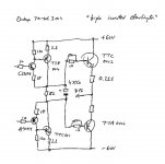
There is something like this used in many higher end Onkyo amps and AVRs such as the TX-NR905 or the TX-NR3009 called the "three stage inverted darlington circuitry", see my atttached drawing.
This circuit has a conventional emitter follower output stage, but the predriver and the driver form a CFP with a gain of 1. The whole amp actually has NFB, but both the LTP and the VAS have resistive loads, so it is probably a low feedback amp. There is no miller compensation and no lead/lag. The dominant pole is achieved by loading the already resistively loaded VAS with a capacitor to ground.
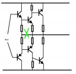
There was also something which looks like an Onkyo engineer tried to explain on a public site:NON-NFB AMPLIFIER
There is only a partial sketch of the output stage. The NPN predriver is followed by a PNP darlington, so driver and output transistor operate common collector. The whole amp was non-NFB.
This second circuit places the output transistor in a local feedback loop, which the first circuit does not do. However, overall it will probably be slower because the output transistor is used common collector.
Attachments
- Status
- This old topic is closed. If you want to reopen this topic, contact a moderator using the "Report Post" button.
- Home
- Amplifiers
- Solid State
- Darlington and Triple darlington