
If you look at even BJTs with a good bandwidth you'll see turn-off times are typically a few µs. This is because of the minority carriers in the base region which take time to drain off to the collector or base contact - going from high forward currents to switched off is delayed due to these "stored charges". Switching distortion shows up at high slew rates, ie full swing HF tones.Turn off distortion occurs because when a transistor is switched on fairly hard it kind of sticks on a bit even when drive is removed. The way to minimuse the effect is to ensure that the base can be pulled down hard and quickly (i.e. reverse biased) to suck out the excess charge.
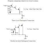
Its probably just about possible to arrange for a CFP to switch off quick, but its quite complex to arrange, as you have to avoid adding cross-over artifacts in the process - I've had a go at doing this and only made THD worse at HF... The emitter-follower with speed-up cap is a natural fit with only benign effect.You cannot do this with CFP because it's impossible to reverse bias the output device. To achieve this with EF output you need to use Self's EF Type II scheme, normal Darlington connection will not achieve the required reverse bias.
A BJT CFP output will normally show visible switching distortion on a scope at ~50kHz signal, although slew-limiting may also show up. At low slew rates the stored charge naturally dissipates before the switch-over so its not normally measurable at low frequencies like 1kHz. Higher currents per device will exacerbate switching distortion, as will older, lower-speed devices.
Member
Joined 2009
Paid Member
A consequence of the slow turn-off is that you risk higher power dissipation at high frequencies because of cross-conduction. I mitigated this with a lower base-rail resistor i.e. higher standing current through the CFP driver.
Parasitic cross-conduction also implies no cut-off in current flow. It has been proposed by some authors that this is a form of non-switching Class B and is desirable. I keep an open mind on this. One design which exploits cross-conduction at h.f. is the KRILL and it generated very positive reports about it's sound signature, especially the treble. It doesn't use a CFP output topology to achieve this.
Parasitic cross-conduction also implies no cut-off in current flow. It has been proposed by some authors that this is a form of non-switching Class B and is desirable. I keep an open mind on this. One design which exploits cross-conduction at h.f. is the KRILL and it generated very positive reports about it's sound signature, especially the treble. It doesn't use a CFP output topology to achieve this.
- Status
- This old topic is closed. If you want to reopen this topic, contact a moderator using the "Report Post" button.