Dirk,
Did you try the I/V resistor before the transformer (your 40 ohms resistor in post #31).
I remember experimenting with this some 12 years ago with my DAC1, which used the PCM63 chip with a 1:5 step up transformer. That gave some 700 mVRMS with a 100 ohm I/V resistor directly at the current output of the chip. I preferred this (sonically) over the I/V resistor at the secondary.
Dirk,
Did you try the I/V resistor before the transformer (your 40 ohms resistor in post #31).
I remember experimenting with this some 12 years ago with my DAC1, which used the PCM63 chip with a 1:5 step up transformer. That gave some 700 mVRMS with a 100 ohm I/V resistor directly at the current output of the chip. I preferred this (sonically) over the I/V resistor at the secondary.
No, I haven't built anything yet. Thanks for your input.
I wonder, can I use the reflected impedance of 62.5 ohms as part of an RC circuit on the primary side such that I only need to add a capacitor across the primary leads (or DAC output)? Then I don't really need C* on the secondary side (except maybe to keep RF out of the op amp)?
I think the notion of 'reflected impedance' only works around the frequencies the transformer is designed to work with. If you have a transformer equivalent circuit model, find out what the leakage inductance is. This will to a large extent determine the upper frequency limit - beyond that the transformer will be a reflector for the input signal, not the output
")
<edit> looking at your schematic, the R and C for RF impedance stabilization should rather be on the DAC side, not the opamp side
Last edited:
I think the notion of 'reflected impedance' only works around the frequencies the transformer is designed to work with. If you have a transformer equivalent circuit model, find out what the leakage inductance is. This will to a large extent determine the upper frequency limit - beyond that the transformer will be a reflector for the input signal, not the output
<edit> looking at your schematic, the R and C for RF impedance stabilization should rather be on the DAC side, not the opamp side
Oh hey, thanks for the help.
Jensen says the transformer has a -3dB point of 180kHz on the high end.
The 47ohms/4700pF is to protect the op amp input, but I could add another RC filter on the primary side of the transformer, set to something like 180kHz. It will have to be a different kind of filter because the DAC is a current source. A resistor and capacitor in parallel with the primary winding would work:
Vout/Iin = R/(1+fRC) - when driven by a current source.
RC circuit - Wikipedia, the free encyclopedia
I've never worked with this before so I could be in error.
It's starting to look more like the Audio Note circuit now...
Would the transformer secondary be considered a current source also? If that's the case then I have to change the 47ohms/4700pF circuit also.
Thanks again for your help.
Jensen says the transformer has a -3dB point of 180kHz on the high end.
Dirk, you can't say this without specifying the source impedance, because HF bandwidth (and also LF) of whatever transformer will be largely determined by source impedance.
Besides, Jensen's spec is for the 4:1 step-down application, not your 1:4 step-up.
In an earlier post I told you that my da converter had 1:5 step up transformers.
I wound the transformers such that there was gentle roll off above some 50 kHz with the 100 ohms I/V resistor determining most of the source impedance.
No extra filtering was needed; actually any effort in that direction did not turn out to be beneficial for sound quality.
One of the advantages of transformer coupling in a dac like this is just the limited HF bandwidth.
I advice to experiment with this.
Last edited:
The 47ohms/4700pF is to protect the op amp input, but I could add another RC filter on the primary side of the transformer, set to something like 180kHz.
Yeah, I reckon 14nF of capacitance in series with 62R gives you this. You'll need to fit that as close to the DAC outputs as possible, to minimize inductance.
Would the transformer secondary be considered a current source also? If that's the case then I have to change the 47ohms/4700pF circuit also.
I'm not very experienced in working with transformers, but I'd guess at 'yes' as the answer to this question. What the trafo 'sees' on its input is reflected at the output. So you shunt the current source with a resistor on the secondary side - that's your 1k. Beyond that you can consider you have a voltage source with an internal resistance of 1k, that's what's driving your 47R/4n7 next stage filter.
Dirk, you can't say this without specifying the source impedance, because HF bandwidth (and also LF) of whatever transformer will be largely determined by source impedance.
Besides, Jensen's spec is for the 4:1 step-down application, not your 1:4 step-up.
In an earlier post I told you that my da converter had 1:5 step up transformers.
I wound the transformers such that there was gentle roll off above some 50 kHz with the 100 ohms I/V resistor determining most of the source impedance.
No extra filtering was needed; actually any effort in that direction did not turn out to be beneficial for sound quality.
One of the advantages of transformer coupling in a dac like this is just the limited HF bandwidth.
I advice to experiment with this.
Thanks for pointing that out. Jensen's test circuits include the 2k43 resistor across the secondary, so yeah, I don't know the bandwidth in my particular circuit.
Please pardon my poor memory, but was your 100ohm I/V resistor on the primary or secondary side of the transformer?
So, maybe it is true that no extra filtering is needed. That would be great if it was the case.
Yeah, I reckon 14nF of capacitance in series with 62R gives you this. You'll need to fit that as close to the DAC outputs as possible, to minimize inductance.
I'm not very experienced in working with transformers, but I'd guess at 'yes' as the answer to this question. What the trafo 'sees' on its input is reflected at the output. So you shunt the current source with a resistor on the secondary side - that's your 1k. Beyond that you can consider you have a voltage source with an internal resistance of 1k, that's what's driving your 47R/4n7 next stage filter.
Thanks for your input. I'm still learning as well of course.
A few things I do know is that I need the 1k resistor because it sets the load impedance for the DAC via the transformer. It doesn't have to be 1k of course, and if there was a resistor on the primary side then I wouldn't need it. The + input to the op amp must have a DC path to ground, but that can be through the transformer. I believe I need the 47ohms/4700pF RC filter to protect the op amp input though. Other things are not really known to me yet.
Please pardon my poor memory, but was your 100ohm I/V resistor on the primary or secondary side of the transformer?
Primary side, right at the current output of the dac chip.
The PCM63 has 4 mA p-p full scale, which is 1.4 mA RMS; the 100 ohms resistor converter to 140 mV; with the 1:5 transformer I reached 700 mV RMS output.
Output impedance 100 x (5²) = 2k5.
I implemented a simple discrete jfet outbuffer to lower output impedance, but some (most tube fanatics) preferred it without the output buffer.
So, maybe it is true that no extra filtering is needed. That would be great if it was the case.
Just try it; that's the fun of DIY, and there is no risk of damaging.
Primary side, right at the current output of the dac chip.
The PCM63 has 4 mA p-p full scale, which is 1.4 mA RMS; the 100 ohms resistor converter to 140 mV; with the 1:5 transformer I reached 700 mV RMS output.
Output impedance 100 x (5²) = 2k5.
I implemented a simple discrete jfet outbuffer to lower output impedance, but some (most tube fanatics) preferred it without the output buffer.
Thank you.
One thing that occurs to me is that if the I/V resistor is on the secondary side, then in the case of a step up transformer, it would be in parallel with the secondary winding, which then lowers the source impedance for the opamp. I think this would lower the noise level a little bit. The way I have it now, the DAC sees 62.5 ohms as a load impedance, and the opamp sees the 1k in parallel with the transformer secondary (which I can't figure out right now but it should be less than 1k) as a source impedance. I did the maths that Sowter showed to figure out the 1k resistor for 0.775 volts @ 0dB output from the DAC which I guess means that I've got too much gain in the opamp, since 0.775x4 = 3.1 volts. Maybe I should either lower the gain in the opamp or lower the I/V resistor value.
Last edited:
Maybe I should either lower the gain in the opamp or lower the I/V resistor value.
Or even throw out the opamp when you can cope with 775 mVRMS.
All you might need is a good simple output buffer then.
My guess this sounds better than with the opamp in.
Or even throw out the opamp when you can cope with 775 mVRMS.
All you might need is a good simple output buffer then.
My guess this sounds better than with the opamp in.
Thanks again for the ideas.
Right now, I think I want the standard 2 volts output for 0dB, or at least I think it's a standard.
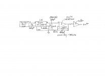
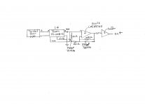
Here's the one I'm going to build. I changed the 1kohm I/V resistor to 750ohms. So, for 0dB output from the DAC I get 2volts output. The 750ohms transforms into about 46ohms as seen by the DAC output. The two filters around the op amp make for a very small phase shift @ 20kHz.
Attachments
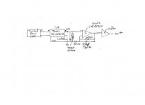
Here's the one I'm going to build. I changed the 1kohm I/V resistor to 750ohms. So, for 0dB output from the DAC I get 2volts output. The 750ohms transforms into about 46ohms as seen by the DAC output. The two filters around the op amp make for a very small phase shift @ 20kHz.
I have two serious concerns regarding the circuit you are planning to build. The first is that the transformer will not present a 46 ohm load to the DAC, it will present a 300 ohm load. Which means that there would be about a 1.1V pk-pk swing at each PCM1794A output pin. While I don't know the low distortion compliance limit of the PCM1794A outputs, I feel fairly certain that you would exceed or be flirting with it.
The second concern is that without an i/v resistor in parallel with the DAC output to establish a reasonable source impedance for the primary, the source impedance will be very high, on the order of a couple megohms for the PCM1794A according to reports I've read. This will cause the transformer to generate very significant distortion.
Last edited:
There are two serious concerns regarding this circuit. The first is that the transformer will not present a 46 ohm load to the DAC, it will present a 300 ohm load. Which means that there would be about a 1.1V pk-pk swing at each PCM1794A output pin. While I don't know the low distortion compliance limit of the PCM1794A outputs, I feel fairly certain that you would exceed or be flirting with it.
The second concern is that without an i/v resistor in parallel with the DAC output to establish the source impedance seen by the primary, the source impedance will be very high, on the order of a couple megohms for the PCM1794A according to reports I've read. This will cause the transformer to generate very significant distortion.
Thanks for your concern. See the DAC page from Sowter:
SOWTER DAC I/V TRANSFORMERS
Thanks for your concern. See the DAC page from Sowter:
SOWTER DAC I/V TRANSFORMERS
I suppose, that the only way you are going to learn is to find out the hard way.
I suppose, that the only way you are going to learn is to find out the hard way.
So, are you saying that the math as presented by Sowter is incorrect? How did you arrive at your number? I showed in a previous post exactly how I did it, and yet you just blurt out some number without any math to back it up.
Second, do you think for a minute that Sowter would risk their reputation by publishing something that was completely wrong or otherwise unworkable?
- Status
- This old topic is closed. If you want to reopen this topic, contact a moderator using the "Report Post" button.
- Home
- Source & Line
- Digital Line Level
- DAC project