Yes, I realized that. The Sabre DAC chips, and nearly all others today, utilize differential outputs which are referenced not to ground but rather, to a D.C. voltage midway between ground and the chip's positive supply rail. The DAC chip industry made this move mostly as a cost saving measure. Only a unipolar power supply is required, rather than the bipolar supply which used to be required.
I'm using the Twisted Pear COD DAC. It uses a TI chip, the PCM1794A. I don't completely understand it but it doesn't appear to have the kind of ground you are talking about.
it really doesnt matter, the resistor still forms part of an RC filter across the primary and performs the IV conversion, or rather in the case of sabre the impedance causes the sabre to perform its own. not the transformer in either case 1865 or 9018
I believe the RC filter on the primary and secondary side of that circuit is to limit the bandwidth to reduce ringing in the transformer, not for I/V conversion. If the input impedance of the transformer were infinite, then yeah of course the resistor would be doing the conversion, but that's not the case here. The impedance is finite and virtually zero at DC, so I don't see how very much current is going to flow through that resistor. If there was a dead short across the resistor, I don't think any voltage would be developed across it.
I don't claim to be an expert in this by any means, so I could be wrong.
Last edited:
what size is this imaginary resistor you arent going to use? if its more than 680R then ALL of the current is converted to voltage
You'll have to ask Audio Note that. I don't have a clue.
So you're saying that if the resistor was infinite (as in not there), then all the current would certainly be converted to voltage? I'm trying to understand this here, not criticizing.
Last edited:
You'll have to ask Audio Note that. I don't have a clue.
So you're saying that if the resistor was infinite (as in not there), then all the current would certainly be converted to voltage? I'm trying to understand this here, not criticizing.
The importance of that resistor in the AN schematic is that it primarily sets the source impedance (in parallel with the DAC's typically high-ish output impedance) as seen by the transformer primary AND limits the voltage swing at the DAC chip output. In that process of limiting the voltage swing it necessarily and dominantly performs the i/v conversion. Yes, the transformer primary is in parallel, so together they form an i/v network, but is the transformer really helping the resistor much? Let's find out.
Okay, let's do some back-of-the-napkin calculations using that Jensen JT10KB-D. First, let's calculate the transformer's reflected impedance as seen by the PCM1794A, and with that op-amp circuit with the 2k43 ohm resistor load on the secondary side. The net secondary load would be: 2,430 ohms + the secondary winding resistance of 92ohms = 2,522 ohms. Now, we multiply this by the square of the turns ratio so, 16 * 2,522 = 40,352 ohms. However, we're not yet done. We have to add the primary's winding resistance. Therefore, 40,352 + 2,500 = 42,852 ohms! Great for connecting to a tube anode, not so much for connecting to a DAC chip's current output pin it looks.
Now, let's calculate the voltage swing which would theoretically be produced by the current output of a PCM1794A, assuming it had the output voltage compliance. It's datasheet says that the 1794A will output 7.8mA peak-to-peak at full scale. Which means, each differential output pin will output half that, or 3.9mA pk-pk. To calculate the resultant pk-pk voltage at each pin we simply multiply 3.9mA * 42,852 ohms = 167 Volts!!
Alright, I think we can conclude two things. One, given that the output voltage compliance of the PCM1794A is probably a few tenths of a volt, although it may be upwards of a volt or so, I'm not sure, an i/v resistor several hundred times smaller than 42,852 ohms would likely be required. Which also means that, while the transformer primary and the i/v resistor do form a parallel network, the current through the i/v resistor will be several hundred times greater than the current through the transformer primary. Two, the JT-10KB-D may not be the best transformer for this application.
Last edited:
The transformer is not designed to connect to a tube annode. It's a balanced line receiver.
I seriously doubt that the TI DAC will put out that kind of current into 40kohms. It'll just put out less current if it's loaded like that.
You seem to be working hard at avoiding my points. In general, you seem less than receptive to guidance for someone who has essentially said that they don't really know much about electronics. Best of luck with your project, just the same.
Last edited:
You seem to be working hard at avoiding my points. In general, you seem less than receptive to guidance for someone who has essentially said that they don't really know much about electronics. Best of luck with your project, just the same.
I didn't have time last night to thoroughly read your post, sorry.
I agree that the Jensen transformer I picked may not be the ideal one for this application. Probably a simple 600 ohm repeat coil would have been better.
Last edited:
From Sowter:
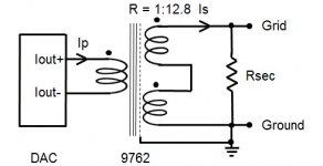
"The Iout + and - should be disconnected from the existing circuit and conected to the primary. The secondary windings should be wired in series and connected between the amplifier grid and ground. The internal electrostatic screen should be connected to analog ground. It is important not to conect the amplifier ground to the digital ground of the CD player. The I/V resistor (Rsec) should be connected across the secondary of the transformer as shown.
HOW TO CALCULATE THE I/V RESISTOR: First calcualte the secondary current (Is). This is given by the primary current ( Ip) multiplied by the inverse of the voltage ratio. If the output current pf the DAC is 4 mA p-p, Is = 4/12.8 = 0.33 mA p-p which is 0.33 / 2.83 = 0.117 mA rms. If we want to get 0 dBu (0.775V) at the grid (Vg) we need:
Rsec = Vg/Is = 775/0.117 = 6.6 kOhms.
NOTES: This will work well provided the secondary feeds a high impedance such as a valve grid. It the load is expected to be low the secondary windings should be connected in parallel and a lower secondary resistor used but of course the output voltage will be lower. It should be apparent that it is possible to adjust the I/V resistor and transformer ratio to get a different output voltage but it should be born in mind that most DACs work best with a low I/V resistor. The value of the I/V resistor as seen by the DAC (the reflected secondary load) can be calculated by dividing by the ratio squired. With a Rsec = 6.6 kOhm the reflected laod will be 6600/12.8^2 = 40 Ohms."
So, for this Jensen transformer (flipped around) with a turns ratio of 1:4, I get about 1kohm as the I/V resistor on the secondary.
Attachments
Last edited:
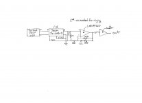
The second thing is, the transformer you've chosen is a 4:1 step down. Given the small signal which will be generated at the primary, you don't want to have the circuit working against itself by having to amplify the signal more than is necessary. So, if you already have possession of this transformer, I suggest that you try reversing the primary and secondary. That is, wire it as a 1:4 step up. You then could reduce the active amplification by a factor of 16! Which doesn't necessarily mean it will produce better sound, but you won't know untill you try.
Yes, I realize now that this is what I have to do. Thanks.
not arguing though...... Ken said it all, this is too hard work for what was a really simple query. i suggest doing some basic reading on electronics that doesnt involve audiophile manufacturers datasheets.
either way i'll be leaving you to it as well
I know enough to be dangerous, as they say... I'm self taught. thanks for your help.
So, for this Jensen transformer (flipped around) with a turns ratio of 1:4, I get about 1kohm as the I/V resistor on the secondary.
and the reflected load as seen by the DAC would be 62.5ohms. I guess that's ok.
I'd hazard that that 62.5ohms is a low frequency value. However the steps coming out of such a DAC have an extremely fast rise time (of the order of nS). To those steps I reckon your transformer (even the wiring before it) will primarily look inductive, not resistive - though there is the matter of proximty effect to consider.... Upshot of this is - the compliance might well be well defined in the audio band but boy, all bets are off at RF frequencies.
I'd hazard that that 62.5ohms is a low frequency value. However the steps coming out of such a DAC have an extremely fast rise time (of the order of nS). To those steps I reckon your transformer (even the wiring before it) will primarily look inductive, not resistive - though there is the matter of proximty effect to consider.... Upshot of this is - the compliance might well be well defined in the audio band but boy, all bets are off at RF frequencies.
OK, thanks. Would you suggest I add a series RC filter (in parallel to the primary windings) set to some RF frequency on the primary side of the transformer?
Yes, it'd be a good start, to get some kind of defined impedance beyond the audio band.
OK, let me work on that. Thanks!
Yes, it'd be a good start, to get some kind of defined impedance beyond the audio band.
I wonder, can I use the reflected impedance of 62.5 ohms as part of an RC circuit on the primary side such that I only need to add a capacitor across the primary leads (or DAC output)? Then I don't really need C* on the secondary side (except maybe to keep RF out of the op amp)?
- Status
- This old topic is closed. If you want to reopen this topic, contact a moderator using the "Report Post" button.
- Home
- Source & Line
- Digital Line Level
- DAC project