If you're using a USB input did you try it with no input connected? I'm assuming your mv readings are AC hum, that's not normal. Try taking readings with no input or output connected.
I took out the caps & reverted to the previous config as in my diagram. With the USB DAC not powered on or connected to the PC but still connected to the trafo most of the hum is gone, I only hear some when I turn the vol up full - this is coming from the amp as I get it even when I disconnect the trafo.
With the USB powered on but not playing I have a hum at low vol.
I have a scope (but don't know how to use it yet. I connected the probes across the grnd & hot wire of the input (with all this connected & turned on) & I get a waveform which goes 5 divisions above the mean & 3 below (Y is et to 0.2V per division) & repeats every 4 and a bit divisions on the X axis (each X div is 1usec. How do I interpret this? That's roughly a 3KHz signal, isn't it?
Edit: Cool Brian, you were one of the people who inspired my trying out transformers on a DAC. I can hear it has great potential behind the hum!
Last edited:
brianco,
Yup. Transformers just hate passive loads. Give them a speaker, or any other kind of complex load and they work ever so much better. You ought to hear what they do for a solid state amp, my oh my.
Bud
Bud, are you talking about coupling speakers to a SS amp with trafos? I never thought of trying that, but after hearing what they do for a DAC I might have to try that. Could you give me a hint what kind of iron I should try?
A little OT but I promise not to do it again.

I took out the caps & reverted to the previous config as in my diagram. With the USB DAC not powered on or connected to the PC but still connected to the trafo most of the hum is gone, I only hear some when I turn the vol up full - this is coming from the amp as I get it even when I disconnect the trafo.
With the USB powered on but not playing I have a hum at low vol.
I have a scope (but don't know how to use it yet. I connected the probes across the grnd & hot wire of the input (with all this connected & turned on) & I get a waveform which goes 5 divisions above the mean & 3 below (Y is et to 0.2V per division) & repeats every 4 and a bit divisions on the X axis (each X div is 1usec. How do I interpret this? That's roughly a 3KHz signal, isn't it?
Edit: Cool Brian, you were one of the people who inspired my trying out transformers on a DAC. I can hear it has great potential behind the hum!
That's a digital signal, if x is set on usec thats millionths of a second,msec is thousandths. Try your probe across the dac chip outputs, plus to minus and see if you can find the hum. Keep unplugging stuff til it disappears to find where it's coming from.
Best I have heard comes from here, http://www.pimmlabs.com/ . The SS Tabor. What Gary is giving away is the first iteration. The second is more dynamic and since it has only O-Netics level three or four iron, it of course sounds much better than before.
In reality, you just need an OPT that will transform the voltage and current to the speakers. You can jump the rail voltage on the amp to good effect and use a step down transformer. A 70 volt line transformer works well here, though you can only find good ones at my door, of course.
Personally I would peruse Edcore and see what they are offering in either a 1:1 or slight step down and try it out for inexpensive.Then, if you like the effect, think about duplicating Gary's amp.
I will say that it is flat out the best sounding amplifier I have ever heard, but that is the rev 2 version he has not published. The rev 1 version was a little bland in character, but that was the only complaint, and it was just a little bland.
Bud
Oops, Bill, told you I couldn't use a scope (I hear you saying it's simple units measure, boy, not a scope problem & I appreciate your bluntness )
Yep, it's on the DAC outs just after the 2.2K across them. And it's gone when I unplug the DAC! I guess it's grunge from the DAC which I need an LPF to get rid of?
)Yep, it's on the DAC outs just after the 2.2K across them. And it's gone when I unplug the DAC! I guess it's grunge from the DAC which I need an LPF to get rid of?
Last edited:
Ok, here's what I did - I unplugged my external power to USB DAC & powered it from the PC through the USB cable. Still I got Hum, still got the same waveform. When I attach the ground probe of the scope to the ground of the input wires , hum stops. Same with external PS to DAC. Even with hum gone I still have the waveform I described.
So I'm just grounding the secondary side of the trafo as per my first diagram (but through the scopes ground now) & no hum. So it would seem the 3MHz signal is not the cause of the hum but it's something I'll come back to, I guess because up full when no hum, I can hear a slight whine.
Hmmmm
So I'm just grounding the secondary side of the trafo as per my first diagram (but through the scopes ground now) & no hum. So it would seem the 3MHz signal is not the cause of the hum but it's something I'll come back to, I guess because up full when no hum, I can hear a slight whine.
Hmmmm
Last edited:
Bud, I have the CCSes built for this amp but don't have the time yet or the heatsinks to build it - I remember your report on visiting his home after an audio meet & listening to the version 1, I presume, which blew your socks off, IIRC? I presume he's holding onto the V2 for own or commercial use?
I guess a grounded amp would solve my hum issues!
Edit:Can I ask a simple question - by grounding the amp am I not just doing the same as I did when I grounded the DAC to the trafo secondary - it's just a longer & more circuitous route?
The grounded SMPS I have powering the DAC also has a 12V out (with a common ground shared with the 5V) - I powered the amp with this & no Hum!!! Viola, as Dell-boy used to say was what the French say ( a UK joke from the a TV comedy series)
Last edited:
Edit:Can I ask a simple question - by grounding the amp am I not just doing the same as I did when I grounded the DAC to the trafo secondary - it's just a longer & more circuitous route?
By grounding the amp with the signal cable, the ground current takes the same path as your signal. Through the audio cable. Bad.
Grounding the amp with the power cable keeps the ground current out of the audio cable. Good.
That is why you want galvanic isolation.
Ok, I can buy that, rossl but would it still be called galvanic isolation if the grounds are ultimately connected? And where does it leave us with the issue of ground loops & noise?
It kind of undermines the concept that the main benefit to all of this is the curing of earth loops & noise?
Edit: I'll do an experiment doing it both ways but I have to say that I haven't noticed a difference sonically between the ground connected to the secondary, as per my first diagram or the amp grounded!
Last edited:
I simply used the + and - outputs from the chip and took these to the transformer primary + and - terminals with two separate wires from the 'o' electrical ground on the DAC board and attached the other ends to the transformer 'ground' terminals. Silent as could be!
Brian, again I don't follow - I must be thick - what's the 'o' ground on the DAC & what are the transformer ground terminals?
Brian, again I don't follow - I must be thick - what's the 'o' ground on the DAC & what are the transformer ground terminals?
Brian was referring to the case and shield grounds of the A-20s. They are not part of the windings in the trafos.
Grounding is such a misunderstood subject that it is sometimes very difficult to discuss unless the same exact terminology is used by all parties. Terms like case ground, chassis ground , PS ground, signal ground, earth ground, can all be very different things to different people. I tend to separate them into two categories, ones that are primarily for safety and ones that are used as a signal return path, but in some cases either can be used as shielding for signals and such. Entire books have been written on the subject. What you never want is a situation where there is an entire path for stray current to circulate such as the shield of an interconnect cable galvanically tied to equipment on both ends that is tied to the chassis, and in turn your house ground wiring. That is worst case, but there are many other scenarios that can occur that can drive you nuts.
I agree, Bill, It's hard to talk about all this without diagrams - hence my continual questions - what's the "o" ground of the DAC?
What do you think of the grounding now working as I stated in my last couple of posts & galvanic isolation (non-)issues?
I'm pretty sure Brian is referring to the O terminal at the +/- 12V PS connecter which is the ground plane on his board, same as mine. It is also the DAC chip ground, or reference point to be more precise, it is not actually grounded to anything else. I did not need to do that, but YMMV. I tied my trafo shields to chassis ground. I would not do both, that would defeat the isolation.
You said that using the same PS for both the dac and amp eliminated the hum, that tells me the problem was a hidden ground loop.
The sound of trafos instead of active devices at the output is what converted me. I have a Rotel player with PCM63s and discrete jfet output stage, and comparing it to the cs4398 with trafos is like comparing a Kia to a Mercedes.
Again, Bill, I agree with your assessment of the sound of the trafos - I'm listening to them now in full splendour, no hum & they are very dynamic & yet natural sounding with lots of detail & speed. Beats the previous opamp o/p stage hands down.
I don't know how it could have been a ground loop when both DAC & Amp were running on non-grounded supplies & Laptop was also running on non-grounded supplies - so only connection between DAC & Amp was through the trafo in a true galvanic isolation?
I don't know how it could have been a ground loop when both DAC & Amp were running on non-grounded supplies & Laptop was also running on non-grounded supplies - so only connection between DAC & Amp was through the trafo in a true galvanic isolation?
Again, Bill, I agree with your assessment of the sound of the trafos - I'm listening to them now in full splendour, no hum & they are very dynamic & yet natural sounding with lots of detail & speed. Beats the previous opamp o/p stage hands down.
I don't know how it could have been a ground loop when both DAC & Amp were running on non-grounded supplies & Laptop was also running on non-grounded supplies - so only connection between DAC & Amp was through the trafo in a true galvanic isolation?
Ah, this is where it gets tricky to talk about. All the units operate with internal virtual grounds, but they are not at the same potential because they are not physically connected. Any potential ground current running through one unit will seek normalising itself with any other unit by any means available, including magnetic coupling through trafos, and also through the PSUs. It is almost Voodoo. It might not technically be a ground loop per-se but it is a loop.
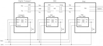
OK, we need a diagram. This is what I use. I hope this works, it is the first time I have tried to post a diagram with the new forum software.
The three boxes have transformers for mains and signal transfer. The only DC connection between the three is star grounding to earth through the 10 ohm resistors. The 10R is enough to prevent stray noise currents from travelling between boxes and earth. All chassis are earth grounded for safety reasons.
The signals are galvanically isolated because signal transformers break any loops between the boxes as far as the power supply noises are concerned. The 10R provides a reference for all the circuits.
Ideally, there will be no current in the 10R resistors after stray capacitance and inductance in the system are discharged through the 10Rs. Hopefully 10R is enough to dampen any interaction between those stray C and L
Only signal currents in the signal cables. Only power currents in the power connections. No mixing of currents.
The 10 ohm resistor should be high enough wattage to blow the fuse in case of a power supply fault. A tiny little SMT resistor may vaporize if the mains shorts to the circuitry.
There is a long article by Rod Elliott about a earthing scheme similar to this
http://sound.westhost.com/earthing.htm
Attachments
Thanks Rossl. With respect to the above diagram, I assume that prudent practice is to tie the transformer metal casing and electrostatic shield (if one exists) for *power* transformers back to the EARTH reference point as indicated in the above diagram?
To what ground is the transformer metal casing and electrostatic shield of a *signal* transformer affixed? Sticking with Bill's terminology, would this be the input or output signal (return path) ground and *not* the Earth reference? This is the way I've seen it done with transformer volume controls.
To what ground is the transformer metal casing and electrostatic shield of a *signal* transformer affixed? Sticking with Bill's terminology, would this be the input or output signal (return path) ground and *not* the Earth reference? This is the way I've seen it done with transformer volume controls.
- Status
- This old topic is closed. If you want to reopen this topic, contact a moderator using the "Report Post" button.
- Home
- Source & Line
- Digital Line Level
- DAC ouput using Transformer