Hey John, glad to see so much discussion here!
Bill is right on. It's a simple circuit and has a lot of advantages. In best practice you should not tie the low point of the secondary to DAC ground, but I have found that sometimes it's the only way to kill the hum. It seems to depend on the power supply of the amp, more than anything. Same amp -different supplies gives different results.
Be a little careful with your center tap connection! measure first. You may have 2.5V on the primary side CT.
You are correct about the Tripath connection. As the input is biased at 2.5V, one end of the transfo needs to be tied to 2.5V, not ground. Otherwise DC would flow thru the winding. The 2.5V end becomes a virtual ground, so to speak.
Keep going, you're on the right path. You'll get there.
It's nice to see so many people getting hip to the transformer output DAC. I love 'em. I sold one for awhile called the "MagiDAC" and have a new one coming out next month thru Virtue Audio. So you can tell I like them.
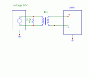
I thought what Bill was saying, in relation to this scheme, that DC should not pass through the trafo?I agree with Bill. The bottom diagram by panomaniac (post 13) should work without hum.
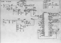
Here's the Lepai Tripath TA2020 schematic. I've since bypassed the whole op-amp input tone control section but haven't hooked up the trafo without grounds - I'll try that. Ohh, so many options now, I'm losing track of them.If you have hum them either something isn't hooked up right or you have a power supply fault. Or a bad transformer.
I say that without knowing what the amp input schematic looks like. Do you have a link to it?
Yep, I like the theory just can't seem to achieve it in practise, (yet!isolating the grounds is the main benefit you will see in using this transformer approach. You shouldn't need to connect grounds between the DAC and amp.
) I guess that's why I started this thread - transformers are well understood in (and well represented) in the tube section but not a lot about them in this configuration.P.S. I'm glad to see no pro/anti transformer wars have started in this thread - let's keep it clean!
Attachments
I thought what Bill was saying, in relation to this scheme, that DC should not pass through the trafo?
Yes, that's what he is saying. And I'm saying that you seem to have a path for energy at the mains frequency getting across the transformer. 50/60 Hz hum. Are the power supply grounds on either side referenced to the mains low wire? floating? earth ground? mains hot?
Here's the Lepai Tripath TA2020 schematic.
You should be able to use the voltage divider as the 2.5V reference for the transformer secondary low wire. It would have been nicer if it was a lower impedance reference, but it should still work.
I agree, nice to see it escaping from the realm of the Tube sectionHey John, glad to see so much discussion here!
Although I must get Shoog's expertise over here as I know he played around with this very thingAh, how I'm powering the Tripath is with a 12V SMPS with no ground pin - hmm, more experimentingBill is right on. It's a simple circuit and has a lot of advantages. In best practice you should not tie the low point of the secondary to DAC ground, but I have found that sometimes it's the only way to kill the hum. It seems to depend on the power supply of the amp, more than anything. Same amp -different supplies gives different results.
Thanks, I think there is 1.4V bias on the DAC differential V outs - ouch, as you say - I'll check. But thinking about it, I wonder if there is a similar 1.4V bias pin I could connect CT to ala the Tripath input stage?Be a little careful with your center tap connection! measure first. You may have 2.5V on the primary side CT.
Yes, that's my understanding - I take it you've tried this & it works? It should also work for the DCA output above?You are correct about the Tripath connection. As the input is biased at 2.5V, one end of the transfo needs to be tied to 2.5V, not ground. Otherwise DC would flow thru the winding. The 2.5V end becomes a virtual ground, so to speak.
Cool, thanks for the postings & encouragement! I will keep going, if I don't blow up something firstKeep going, you're on the right path. You'll get there.
It's nice to see so many people getting hip to the transformer output DAC. I love 'em. I sold one for awhile called the "MagiDAC" and have a new one coming out next month thru Virtue Audio. So you can tell I like them.
It may be the SMPS power supply (with no ground) I'm using?Yes, that's what he is saying. And I'm saying that you seem to have a path for energy at the mains frequency getting across the transformer. 50/60 Hz hum. Are the power supply grounds on either side referenced to the mains low wire? floating? earth ground? mains hot?
There is a biascap pin 14 which outputs the 2.5V (currently running to ground through a cap) - this may be a lower impedance source & where this trick usually takes it's 2.5V reference from.You should be able to use the voltage divider as the 2.5V reference for the transformer secondary low wire. It would have been nicer if it was a lower impedance reference, but it should still work.
It may be the SMPS power supply (with no ground) I'm using?
If the SMPS is transformer isolated, you should be able to connect the amp ground to earth ground, either directly or through a 10 ohm 1/2 watt resistor.
Then if your DAC power supply is also transformer isolated, connect DAC ground to earth the same way.
That should kill the hum.
If the SMPS is transformer isolated, you should be able to connect the amp ground to earth ground, either directly or through a 10 ohm 1/2 watt resistor.
Then if your DAC power supply is also transformer isolated, connect DAC ground to earth the same way.
That should kill the hum.
That could work brilliantly, but dont ground any part of the secondary wiring at the DAC chassis or you will create a ground loop.
I'm not sure, but I presume the SMPS is isolated as you say (I can't open it up without breaking into it)If the SMPS is transformer isolated, you should be able to connect the amp ground to earth ground, either directly or through a 10 ohm 1/2 watt resistor.
This could be the tricky one as it's a USB DAC which I'm running from a Dell laptop. I can't run this on batteries as my laptop battery is busted & I'm not paying for another exorbitant laptop battery. But I think the Dell laptop power supply is not connected to earth - I'll check it out?Then if your DAC power supply is also transformer isolated, connect DAC ground to earth the same way.
That should kill the hum.
Ohh, more experiments - I better start doing something & report results.
Lets see, first off, I'll try this last one - so earth the AMP ground, earth the DAC ground connect the trafo as in Panomaniacs top diagram. This seems to be the best bet.
I'm not sure, but I presume the SMPS is isolated as you say (I can't open it up without breaking into it)
This could be the tricky one as it's a USB DAC which I'm running from a Dell laptop. I can't run this on batteries as my laptop battery is busted & I'm not paying for another exorbitant laptop battery. But I think the Dell laptop power supply is not connected to earth - I'll check it out?
Ohh, more experiments - I better start doing something & report results.
Lets see, first off, I'll try this last one - so earth the AMP ground, earth the DAC ground connect the trafo as in Panomaniacs top diagram. This seems to be the best bet.
There is a big difference between earth and signal ground. If your amp chassis is earth grounded do not ground anything on the secondaries inside the DAC chassis, let the amp take care of that.
Just a note to clarify the "load" issue with reference to transformers. The inductance is what provides the load to the driver and driven stage. As an example, with Dave's fine product, with 130 henries of inductance out into the permeability range, this unite will provide a 15k load all it needs to have to provide - 3db @ 20 Hz. To obtain -0.5 db would require 2.76 times this inductance. So, these are 5k to 5k transformers at -0.5 db @ 20 Hz.
The AC drive signal can be ignored so long as it remains at the typical DAC level. To handle DC voltage is a non issue, but as little as 5ma dc current will cause core saturation at low frequencies and they will roll off.
Bud
The AC drive signal can be ignored so long as it remains at the typical DAC level. To handle DC voltage is a non issue, but as little as 5ma dc current will cause core saturation at low frequencies and they will roll off.
Bud
There is a big difference between earth and signal ground. If your amp chassis is earth grounded do not ground anything on the secondaries inside the DAC chassis, let the amp take care of that.
Sorry, Bill, my mistake in saying I'm using Panaomaniacs top diagram schema - I should have checked first, I forgot it had the ground wire from the amp abck to the primary. Here's my intended topology attached.
I checked & neither the amp chassis or DAC chassis are earthed!
Attachments
Thanks Bud, for dropping in - I hate to be a pain but are these trafos -0.5db@20Hz or -3db @20Hz?Just a note to clarify the "load" issue with reference to transformers. The inductance is what provides the load to the driver and driven stage. As an example, with Dave's fine product, with 130 henries of inductance out into the permeability range, this unite will provide a 15k load all it needs to have to provide - 3db @ 20 Hz. To obtain -0.5 db would require 2.76 times this inductance. So, these are 5k to 5k transformers at -0.5 db @ 20 Hz.
With a 15 kZohm load they are -3db @ 20 Hz and with 5 kZohm load they are -0.5 db @ 20 Hz.
You take the inductance X 2 pi X frequency of interest to get the -3 db impedance figure of merit. Then take that number and divide by 2.76 to obtain the -0.5 db impedance load. This is not the inductance that you get from measuring it on a fixed 120 Hz X 1 vac inductance bridge. That is remenent inductance.
This figure of merit should come from the permeability number provided by the core, at working inductance. In a general sense you can expect at least 10 times working inductance versus what you measure for remenent inductance. This is for commercial grades of steel core. Nickle and amorphous core have greater than 10 X permeability excursion in the working range.
Also note that having more or less than 2 times the needed inductance, for - 3db, will increase distortion. So, a -1 db at the frequency of interest is your lowest distortion point for transformers. This would mean that an 8 k load would give you -1db and the lowest distortion at 20 Hz from Dave's transformer.
Bud
Thanks again Bud, I understand now - although understand is overstating it - I will study what you said & hope to understand it, eventually. So for lowest distortion should I put a 8K load across the secondaries instead of a 2.2K? You see, by my questions, that I'm a simpleton.
I made progress - found a 5V SMPS with a ground connection through to the neg pole for powering the DAC, did the connections as per the diagram & it works but still some buzz. I feel it may well be the SMPS. Why not use a linear supply? Well, the high voltage tolerance on the Tripath is around 13.5 and I tried a 12V linear that measured 15V unloaded, plugged it in while measuring the voltage & it didn't drop so I pulled it. - no damage done - I don't have any 5V linear supply for the DAC.
I may well build two Salas shunt regs - these were in my plans just not yet!
Edit: I measured across the differential out of the DAC & there's something like 4mV & 7mV on the other channel - could this be what I'm hearing? I have a scope - is there any measurements I can do to check this. Could I put a cap in series in each leg to block the DC?
Last edited:
With a 5 k Z ohm load on the primary you can put whatever works best on the secondary. A transformer has two loading mechanisms. One is considered the load line in amplifiers and is provided by the turns ratio and the secondary load in Z ohms, often called reflected load or impedance.
The second is the actual AC voltage and current, in tubes listed as transconductance, and often called mhos.
These two, added in parallel, with the primary DCR added in series and the reflected secondary DCR added in series, provide the total impedance that the primary must match with inductance. So, this is more complicated than just having one number and putting a resistor across the secondary.
The Intact transformer, without any resistor in the primary or secondary circuits, is already providing a -0.5 db load on the device attached to the primary, if that device is an actual 5 K load. This can be a 5 K resistor in series with the primary, between the primary and the driver device. This can also be a tube plate, or any other device.
This is why Pano puts a series resistor in the primary circuit of his buffers, to provide a bigger load to the transformer, to knock down any high Q peak, usually above 25 kHz, from a mismatch in load to the primary which a 600 ohm OPAMP or 100 ohm DAC chip will provide.
Putting a load resistor on the secondary will just kill all of the dynamics. Just leave it alone and let the down stream items load it.
Bud
Last edited:
Thanks Bud,
You're generous with your time & explanations.
I tried the caps in series on each leg but I get real hum with that config & no mV across the diff legs after the caps?
If you're using a USB input did you try it with no input connected? I'm assuming your mv readings are AC hum, that's not normal. Try taking readings with no input or output connected.
............Putting a load resistor on the secondary will just kill all of the dynamics. Just leave it alone and let the down stream items load it.
Bud
I have been following this from the 'other' thread. My A-20 transformers - fed from the chip - were loaded pretty well to the Jensen suggestions. What Bud says makes a lot of sense, so I disconnected the secondary loading. The subjective result is that the image is far more precise with the individual instruments more sharply etched. I listen mainly to classical music and most of all to chamber music. Prior to this change the top end was restricted - a bit constipated and inclined to glare when more than one instrument was in the higher registers. This effect has now totally gone! The top end is now sweet, totally uncluttered. BIG improvement!
Thanks Bud!
John,
Hope your grounding problem gets resolved. I simply used the + and - outputs from the chip and took these to the transformer primary + and - terminals with two separate wires from the 'o' electrical ground on the DAC board and attached the other ends to the transformer 'ground' terminals. Silent as could be!
- Status
- This old topic is closed. If you want to reopen this topic, contact a moderator using the "Report Post" button.
- Home
- Source & Line
- Digital Line Level
- DAC ouput using Transformer