Oh, sorry Mayday. YMMV = Your mileage may vary. Just means your results may be different from mine. Point taken on the English. Your doing very well on your post.
Aha, ok got it
")
Thanks!
Btw, do you have the complete schematic incl. PS?
Some questions about the PCB
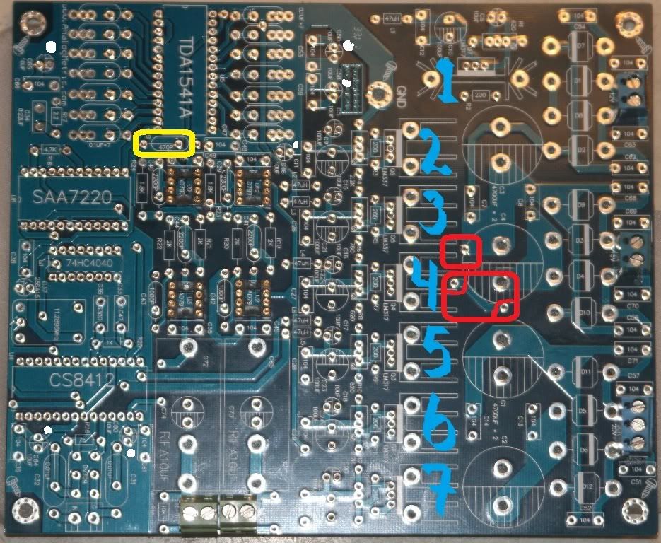
The regs, numbered in the pic, which one feeds what?
The items marked red, are they jumpers or what are they?
Yellow isn't really a questione but rather the DEM cap, which I'll probably use 122pF 1% silver mica.
elcos marked with a white dot, are these suitable spots for Os-cons?
The regs, numbered in the pic, which one feeds what?
The items marked red, are they jumpers or what are they?
Yellow isn't really a questione but rather the DEM cap, which I'll probably use 122pF 1% silver mica.
elcos marked with a white dot, are these suitable spots for Os-cons?
Hi Mayday, You can get a PDF of the schematic and build sheet from Analogmetric. Just email them. Note: There are some errors in there on the schematic. Some polarities are shown wrong on the negative power supply decoupling. The circuit boards are correct so no worries. If you can't get it (the schematic), just PM me with your email and I will send it to you. Stay warm lots of fluids and you should feel better soon. Dave
Hi Mayday, 1 is the SAA7220 regulator, measure at L1 to set to 5 VDC. 2 is -15 VDC regulator for the TDA1541, measure from L2 to adjust. 3 is -5 VDC regulator, measure L3 and adjust. 4 is +5 VDC for the TDA1541, measure from L4 and adjust. 5 is the (2) +5 VDC supplies at the CS8412/8414, measure at either L5 or L6 to adjust. One regulator feeds both L5 and L6. 6 is the analog stage +18 VDC, measure from C29 to set that one. 7 is the analog -18 VDC, measure at C30 to adjust that one. The red boxes your looking at the circuit board vias. That carries power from one side of the board to the other. Hope that helps. Dave
Hi Mayday, 1 is the SAA7220 regulator, measure at L1 to set to 5 VDC. 2 is -15 VDC regulator for the TDA1541, measure from L2 to adjust. 3 is -5 VDC regulator, measure L3 and adjust. 4 is +5 VDC for the TDA1541, measure from L4 and adjust. 5 is the (2) +5 VDC supplies at the CS8412/8414, measure at either L5 or L6 to adjust. One regulator feeds both L5 and L6. 6 is the analog stage +18 VDC, measure from C29 to set that one. 7 is the analog -18 VDC, measure at C30 to adjust that one. The red boxes your looking at the circuit board vias. That carries power from one side of the board to the other. Hope that helps. Dave
Thanks!
That's very helpful.
All regs except 6 & 7 are more or less "static" like you described a few posts above? So for them I can go 22-33uF, and for 6&7 maybe a bit higher?
At what positions on the PCB would you use solid polymer caps?
The bom says 10uF for the ones I think are suitable for SEPC caps, but in my CD-60 I've started swapping 33uF elcos for 270uF SEPC around digital IC's.
Hi Mayday, Yes... I think that 22 or 33 uF bypasses should be good. The digital chips like the 7220 run lots of current as it is a CMOS part. So that regulator will run "Hot" compared to the others. I haven't tried the capacitors you mentioned however they are excellent quality. You might consider for the analog supplies to the Opamps applying smaller caps right near the chips themselves as opposed to using a larger values near the regulators. If you look closely you can see the caps near the regulators are a long distance away. That will help dynamic current delivery. Maybe someone else has a comment on those Polymer capacitors.... Dave
Just been told that if I want to put a tube output stage directly after the tda I need to use something like a 12,5R i-v resistor after it. This giving about 25mV out meens I need 40-80x gain in the outputstage.
I'd like to try to build a tube output atleast, just to see if I like it as much as other tube stuff I've heard. Might not be for this dac, might be for one of my tda1541a based cd-players.
I'd like to try to build a tube output atleast, just to see if I like it as much as other tube stuff I've heard. Might not be for this dac, might be for one of my tda1541a based cd-players.
Last edited:
There's the analog metric site, and after me asking the ebay seller e-mailed me the BOM.
But as for what was shipped, just the pcb.
Astonished
Astonished
Yes, no great level of support at all.
Decided to go with WIMA MKP4 for all the 100nF caps. I think that's a nice choice.
10000uF Dubilier 25V caps pre-regs. (40000uF PS in a DAC lol)
Sanyo OS-con 22uF and 100uF for the regs.
DV709
25pcs Rubycon ZL 470uF/25V
Some resistors and the inductors
That I think is what I'll have to spend on the DAC build in januari.
10000uF Dubilier 25V caps pre-regs. (40000uF PS in a DAC lol)
Sanyo OS-con 22uF and 100uF for the regs.
DV709
25pcs Rubycon ZL 470uF/25V
Some resistors and the inductors
That I think is what I'll have to spend on the DAC build in januari.
I came across this User Guide a while ago, it's from the Analogue Metric site so my apologies if you've seen it already (or indeed if someone else has posted it!) - I'm not feeling my best at the moment either :-(
Thank you! I didn't have that and when I emailed they said the only had the BOM and what was on the site.
Room for some improvement in their customer service....
- Status
- This old topic is closed. If you want to reopen this topic, contact a moderator using the "Report Post" button.
- Home
- Source & Line
- Digital Line Level
- DAC build TDA1541A/SAA7220P/B *will take som time*