You could - it would work. But the available current is way beyond what's called for. As a result of being over-sized for the job its going to be rather prone to mains-borne interference.
So, bigger isn't always better!?!

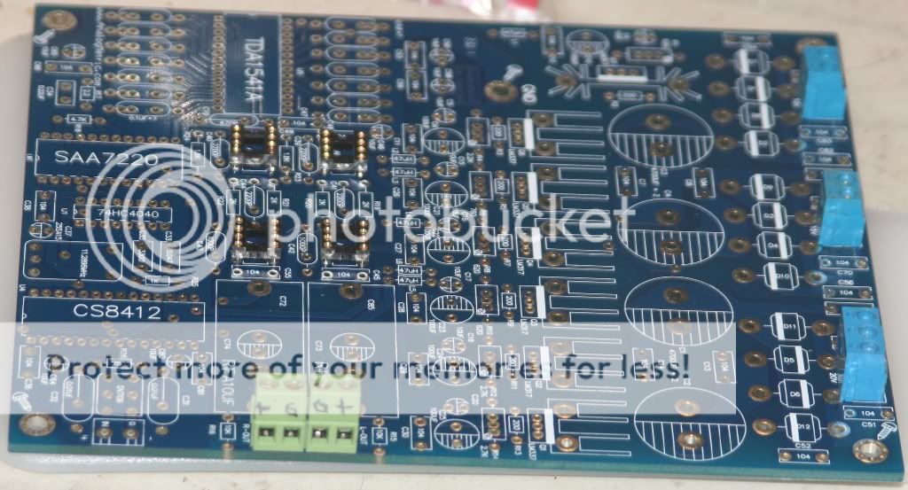
Hi Mayday, I've built one of these and I am working on a second. My first one works without any ticks of any kind. I wasn't that lucky on the second one. What I did was to populate the digital and power supply sections. I didn't build the filter (analog) section. That is anything after the DAC. My DAC uses a NPC filter with glue logic instead of the 7220. I'd have to look at it to get the chip number. I'm using a Hagclock at 11.2896 Mhz. CS8412's not CS8414. I take the DAC out to OPA603 I/V convertor with 7th order GIC Bessel filter from a very old Audio Amateur magazine issue. The output buffer is an OPA627. The I/V+ filter and buffer once lived in my dead CDB650 Magnavox CD player so I did some recycling. I call it the 1541Dacasarus Rex. It sounds real nice. My second build has the clicks so I will probably have to do something different there. I just finished building a Sheldon Stokes 192 KHZ, CS4398 DAC with Lundahl LL1694 transformers. I'm shocked at how similar they sound. Really surprising. I'm leaning toward doing an AD844 Pedja I/V into LL1694 transformers for my second 1541A build. Dave
It sounds real nice. My second build has the clicks so I will probably have to do something different there. I just finished building a Sheldon Stokes 192 KHZ, CS4398 DAC with Lundahl LL1694 transformers. I'm shocked at how similar they sound. Really surprising. I'm leaning toward doing an AD844 Pedja I/V into LL1694 transformers for my second 1541A build. DaveHi Mayday, The ticks? Well I have a few ideas. I'm thinking I may need to adjust the Hagclock frequency. I'll have to install a trim capacitor instead of the 39 pF fixed one in the oscillator tank circuit. I've read that the Analogmetric design with regard to the upsampler is a little suspect. Again my first one works perfect.... In my second build the NPC digital filter has different glue logic chips. The glue logic is used to fix timing to make it I2S compatiable. My cousin made the NPC filter solutions back in the late 1980's. In my second build the logic chips are actually faster then those in my first DAC. I think I need to borrow a frequency counter and check to see if the clock is off frequency. At least compared to the first one. It sounds like the Valab clock is a very good one. 1 PPM is excellent. I'd go with that. I do like your tube output plan. That will give you awesome headroom. I might give that a try in the future. Pictures? I need a few days however that is doable. I need to see if my wife left her digital camera. She's visiting family in China. The only advantage with the hagclock is that it's discrete so tweaking it is an option to try to get rid of the ticks. If that is the issue.... Dave
The only advantage with the hagclock is that it's discrete so tweaking it is an option to try to get rid of the ticks. If that is the issue.... DaveHi Mayday, The ticks? Well I have a few ideas. I'm thinking I may need to adjust the Hagclock frequency. I'll have to install a trim capacitor instead of the 39 pF fixed one in the oscillator tank circuit. I've read that the Analogmetric design with regard to the upsampler is a little suspect. Again my first one works perfect.... In my second build the NPC digital filter has different glue logic chips. The glue logic is used to fix timing to make it I2S compatiable. My cousin made the NPC filter solutions back in the late 1980's. In my second build the logic chips are actually faster then those in my first DAC. I think I need to borrow a frequency counter and check to see if the clock is off frequency. At least compared to the first one. It sounds like the Valab clock is a very good one. 1 PPM is excellent. I'd go with that. I do like your tube output plan. That will give you awesome headroom. I might give that a try in the future. Pictures? I need a few days however that is doable. I need to see if my wife left her digital camera. She's visiting family in China.
The idea of using a pair of ECC86 as output stage is really getting glued in my head(as if I didn't have enough on my plate diy-wise allready).
I have used tube equipment before, even mildly modified it, but never built it.
I guess the easiest way would be to get a PCB that has space for everything needed to connect it straight to TDA1541A output. (think it might be called I/V stage? New to dac-building and tube-building...jumping in to the deep end here lol)
Have no clue where or what to look for though.
Hi Mayday, Well don't be in a big rush. Take a look at other peoples projects for some ideas. Plan and plan and I would advise a step by step approach. If you can break up your project into stages it helps. Oh, and sometimes things don't go as planned. I know of several DAC projects out there using the TDA1541A. There is the lampizator website. He likes the minimalist approach so that should be fairly easy to duplicate. He tends toward non oversampling. This can work if your preamp and amplifier are limited in upper frequency response. So if you use tube gear then that might be worth looking at. Google is your friend. My homemade preamp is really flat, I have not measured it yet however I think it goes out beyond 10 MHZ. So in my case a reconstruction filter is needed. My class T amp by design limits that stuff. So if you have a working CD player based on the 1541. I would consider building your proposed tube stage. Install it on your existing player and debug it and in the mean time work on your new board. Anyway you do it have fun. This is a great hobby. On my second build I'm thinking of buffering the hagclock and running one output to the Analogmetric board and the other to a transport /CD player to lock step them. Someone at my Audio club gave me their old CDB650 Magnavox CD player. Since they both have 11.2896 MHZ clocks this makes sense to me. One issue... I have to find the source of the smell in the player first. As I mentioned there is always something. It works so I hope that's a minor thing. So it sounds like you have the clock figured out. You know you want a tube stage. So do you want to do oversampling or non-oversampling? Once you start deciding things it should all fall into place. Dave
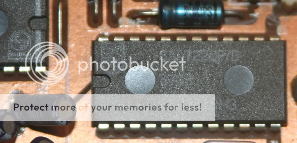
Plan and plan and I would advise a step by step approach. If you can break up your project into stages it helps. Oh, and sometimes things don't go as planned. I know of several DAC projects out there using the TDA1541A. There is the lampizator website. He likes the minimalist approach so that should be fairly easy to duplicate. He tends toward non oversampling. This can work if your preamp and amplifier are limited in upper frequency response. So if you use tube gear then that might be worth looking at. Google is your friend. My homemade preamp is really flat, I have not measured it yet however I think it goes out beyond 10 MHZ. So in my case a reconstruction filter is needed. My class T amp by design limits that stuff. So if you have a working CD player based on the 1541. I would consider building your proposed tube stage. Install it on your existing player and debug it and in the mean time work on your new board. Anyway you do it have fun. This is a great hobby. On my second build I'm thinking of buffering the hagclock and running one output to the Analogmetric board and the other to a transport /CD player to lock step them. Someone at my Audio club gave me their old CDB650 Magnavox CD player. Since they both have 11.2896 MHZ clocks this makes sense to me. One issue... I have to find the source of the smell in the player first. As I mentioned there is always something. It works so I hope that's a minor thing. So it sounds like you have the clock figured out. You know you want a tube stage. So do you want to do oversampling or non-oversampling? Once you start deciding things it should all fall into place. DaveI'm going with OS for the time being as I've heard that if SAA7220 gets its own PS, that's the way TDA1541A sounds best.
ATM I use Arcam Alpha 8 integrated and Alpha 8 power amp.
The power amp driving the Dayton 15" IB's in my dipoles and the integrated driving the top(B&G NEO8 and Dayton Reference 7" ).
The DAC build will take some time anyways since I gather parts as I find/can afford them
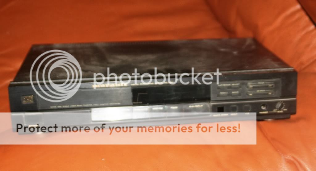
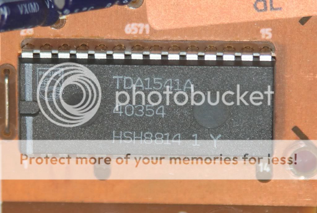
I actually have 3 working cd-players w TDA1541A/SAA7220P/B now, CD-50, CD-60 and CD-75mkII.
The only one modded, so far mildly, is the CD-60.
I know a few tube/valve gurus...I'll ask them about outputstage for CD/DAC.
ATM I use Arcam Alpha 8 integrated and Alpha 8 power amp.
The power amp driving the Dayton 15" IB's in my dipoles and the integrated driving the top(B&G NEO8 and Dayton Reference 7" ).
The DAC build will take some time anyways since I gather parts as I find/can afford them
I actually have 3 working cd-players w TDA1541A/SAA7220P/B now, CD-50, CD-60 and CD-75mkII.
The only one modded, so far mildly, is the CD-60.
I know a few tube/valve gurus...I'll ask them about outputstage for CD/DAC.
Hi Mayday, Sounds like your pretty well set with 1541 Dacs. So far I'm sticking with OS as well. My main system has Magnepan MG2.5R planar ribbon speakers with custom passive crossovers. The amp is a Sure class T with some mods. 100 Watts into 4 ohms per channel. The Sure is OK if you cut the ceramic coupling caps out and use a MKT cap instead. Preamp is home made chip preamp. AD843/Buf03 running pretty much near class A. HOT!!!! So far no issues. I'll be getting that into a nice enclosure one of these days. For that clicking or tick problem (my second build) I think slaving the CDB650 to the Analogmetric DAC should solve that. My understanding is the over run and under run of the SPDIF input clock versus the clock in the Analogmetric DAC is the source of that noise. Why my first build doesn't tick is still a mystery. I've used an OPPO BDP-83SE as a SPDIF source as well as the Magnavox CDB650 and a Sony Bluray network player with no noises or issues (SPDIF over coax, no Toslink). Oh, and Happy New Year to all. Dave
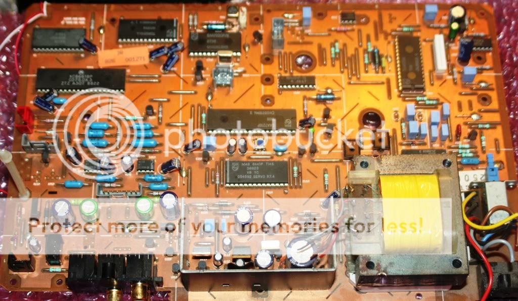
So far I'm sticking with OS as well. My main system has Magnepan MG2.5R planar ribbon speakers with custom passive crossovers. The amp is a Sure class T with some mods. 100 Watts into 4 ohms per channel. The Sure is OK if you cut the ceramic coupling caps out and use a MKT cap instead. Preamp is home made chip preamp. AD843/Buf03 running pretty much near class A. HOT!!!! So far no issues. I'll be getting that into a nice enclosure one of these days. For that clicking or tick problem (my second build) I think slaving the CDB650 to the Analogmetric DAC should solve that. My understanding is the over run and under run of the SPDIF input clock versus the clock in the Analogmetric DAC is the source of that noise. Why my first build doesn't tick is still a mystery. I've used an OPPO BDP-83SE as a SPDIF source as well as the Magnavox CDB650 and a Sony Bluray network player with no noises or issues (SPDIF over coax, no Toslink). Oh, and Happy New Year to all. DaveYes, got a PCB from a CD-75mkII aswell, this is where I'll take the TDA/SAA to the DAC.
Using DIY dipoles w Dayton 15" IB, Dayton Reference 7", NEO8, xover is all PIO, Silverwire and copper air core inductors.
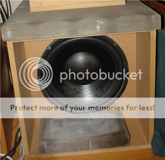
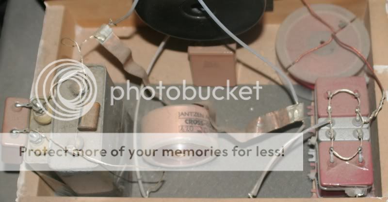
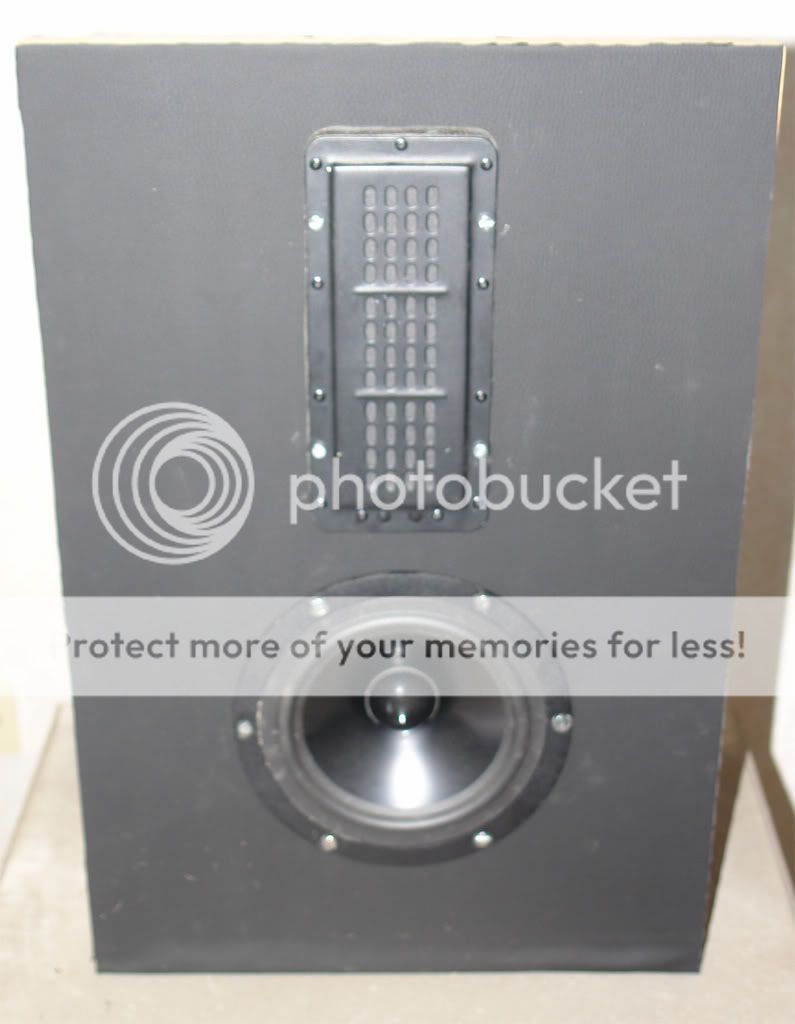
In this pic I still used the SEAS P17RCY 6,5", now replaced w the dayton 7"
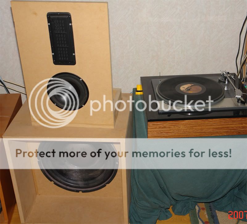
Was only setting the speakers up to test them 3 years ago or so, still haven't gotten around to making them look pretty lol!
And Happy new year!

Using DIY dipoles w Dayton 15" IB, Dayton Reference 7", NEO8, xover is all PIO, Silverwire and copper air core inductors.
In this pic I still used the SEAS P17RCY 6,5", now replaced w the dayton 7"
Was only setting the speakers up to test them 3 years ago or so, still haven't gotten around to making them look pretty lol!
And Happy new year!
Got some oscon sepc to spare after I've soldered a few into the cd-60.
They are 270uF/16V.
They should be as good for this DAC as they are for tda1541a cd-players?
Even if it takes longer to afford the parts, I'll try to use the best options awailable since this dac will stay in my stereo for years if I get it good enough.
They are 270uF/16V.
They should be as good for this DAC as they are for tda1541a cd-players?
Even if it takes longer to afford the parts, I'll try to use the best options awailable since this dac will stay in my stereo for years if I get it good enough.
The BOM calls for 10uF/50V Nichicons (incl. around digital IC's), decoupled by 100nF wima.
But I'm thinking that I'd be better of using 22uF/20V Solid polymer caps around digital IC's and Rubycon ZLH for the rest of them(BOM calls for a total of 11pcs of 10uF caps).
I guess I should stick to the specified 10uF around regs, but the others can't hurt to go higher, maybe even higher than 22uF, right?
Still using the wimas of course.
Before regs bom calls for 6800uF nichicon gold, but I was thinking either:
Rubycon MXC 10000uF/25V(25mm diameter) or Rubycon MXC 6800uF/35V(25mm diameter) or getting Nichicon KG gold tune 6800uF/35V(20mm diameter).
There are other options too:
ELNA LAH 10000uF/35V(22mm diameter) is one.
Jamicon LPW 10000uF/25V(22mm diameter) is another.
Maximum diameter for pre-reg caps is 22mm, could maybe squeeze in 25mm caps...
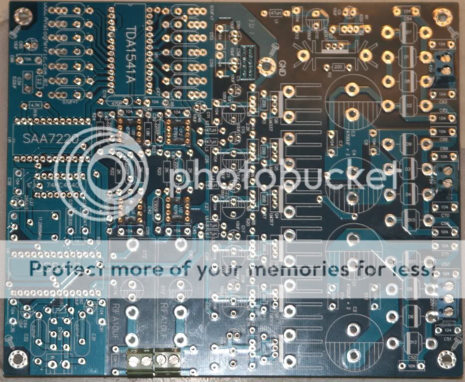
Don't get why they reserved so much space for the rect. diodes??
But I'm thinking that I'd be better of using 22uF/20V Solid polymer caps around digital IC's and Rubycon ZLH for the rest of them(BOM calls for a total of 11pcs of 10uF caps).
I guess I should stick to the specified 10uF around regs, but the others can't hurt to go higher, maybe even higher than 22uF, right?
Still using the wimas of course.
Before regs bom calls for 6800uF nichicon gold, but I was thinking either:
Rubycon MXC 10000uF/25V(25mm diameter) or Rubycon MXC 6800uF/35V(25mm diameter) or getting Nichicon KG gold tune 6800uF/35V(20mm diameter).
There are other options too:
ELNA LAH 10000uF/35V(22mm diameter) is one.
Jamicon LPW 10000uF/25V(22mm diameter) is another.
Maximum diameter for pre-reg caps is 22mm, could maybe squeeze in 25mm caps...
Don't get why they reserved so much space for the rect. diodes??
Hi Mayday, I hope your feeling better. On the capacitor question.... On the input side of regulators large is better. On the output side you want to balance dynamic regulation against static regulation. So if I'm regulating a device with a fairly fixed current draw like a digital chip I'd consider using using maybe 3 times larger then what is shown in the schematic. So I'd replace a 10uF cap with a 22 or 33 uF. For a dynamic load say an Op amp I'd have to consider dynamic power demands. Bass response etcetera. In my recent Preamp I went double and ended up at 220 uF on each rail and 470 uF on the Buf 03. Plastic film capacitor bypasses in all cases. Not very scientific however I don't think you can wrong with this. One weird finding on my old GIC filter, I found all electrolytics were actually audible on the supply rails so I went with all plastic film bypasses highest practical value and went for dynamic regulation. No electrolytics on that board at all. Of course YMMV. Dave
Dave- Status
- This old topic is closed. If you want to reopen this topic, contact a moderator using the "Report Post" button.
- Home
- Source & Line
- Digital Line Level
- DAC build TDA1541A/SAA7220P/B *will take som time*