analog metric tda1541a
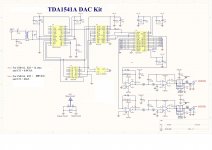
There are many mistakes in their scheme and missing components
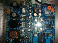
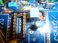
The "socket" it is a small relay to switch from electrical in to optical in and D13 is one 1n4148 dc protec and j is for a sw (open is for electrical in) that switches from electrical to optical in.
Here is a picture of my board im still making testes
There are many mistakes in their scheme and missing components
The "socket" it is a small relay to switch from electrical in to optical in and D13 is one 1n4148 dc protec and j is for a sw (open is for electrical in) that switches from electrical to optical in.
Here is a picture of my board im still making testes
Attachments
Very good
Hey thanks a lot , now i have hope my board will work if you help me a bit.
I was checking your photo and i saw some differences, maybe i'll check carefully and ask you.
If you have a correct part list or modifications to do please send me.
Can you tell me what kind of relay i should buy (maybe part number)
I saw you made NOS, i tryed but mine don't works, but i saw you removed XTAL and 75HC4040 maybe thats why mine don't work.
TDA1541A DAC AND NOS MODE
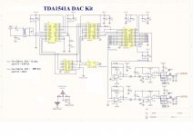
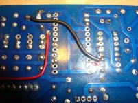
This is my second change to original schematics.
If you find anything wrong please inform.
There are 3 grounds analogue, digital, and chassis ground.
In the pcb, analogue and digital ground they are shunted.
See the pics for the change.
I have not made yet any test only check the grounds and there circuit.
Attachments
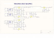
TDA1541A DAC psu
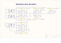
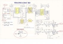
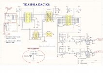
This are my last finding on the power supply and dac board.
I'm amazing whit the mistakes not only in the schematics but also in the Psu drawing.
May be it is best to test everything and then post here.
This Chinese are amazing, i I do not understand how it all worked before with so many errors.
Wrong grounds wrong dc (analogue and digital) supply
Anyway this are my last findings
Attachments
Hi MANEP, The schematic is really bad. The board is more or less sort of correct. It has less errors. Your also correct about the SPDIF input, the resistor must be across the coax to properly terminate it. If you want low jitter. On my build (I have 2) I skipped the entire analog stage. I also removed the reclocker since it barely works. I used a DIR9001 adapter board that replaces the CS8412. Jumpered the master clock to the SAA7220 socket. I made an adapter to use a NPC SM5814 digital filter. The DIR9001 has 2 modes I2S 24 bit and 2's complement Sony mode 16 bit. I used the Sony mode. The NPC chip outputs I2S to the TDA1541A. There are other options other then NOS. This is how I did it. The DAC benefits from better grounding around the DAC. Check out ECDesigns thread. I made a board that allows PPS surface mount capacitors under the chip for very short ground paths. Hope that helps. Regards... Dave
confused
I bought this board a couple of years back. I have been struggling with it ever since. I have ripped out the input transformer and put a 75 ohm resistor across the cable. I can now see a signal from the transport. I removed the SAA7220 to follow mod 1. I can see data on pin 3 of the TDA1541, but nothing on pins 2 and 4. On the left channel of the dac I get noise, but nothing on the right. It appears the onboard clock does not work. Should I continue to mod 2 by removing the 74HC4040 and the crystal or try a different clock?
Hi
It is best to put de DAC in a NOS mode (without the SAA) and better output amps like OPA627 and also a low jitter clock.
The sound it will be much better.
I bought this board a couple of years back. I have been struggling with it ever since. I have ripped out the input transformer and put a 75 ohm resistor across the cable. I can now see a signal from the transport. I removed the SAA7220 to follow mod 1. I can see data on pin 3 of the TDA1541, but nothing on pins 2 and 4. On the left channel of the dac I get noise, but nothing on the right. It appears the onboard clock does not work. Should I continue to mod 2 by removing the 74HC4040 and the crystal or try a different clock?
Hi msmart2b, I agree with erin. Junk the clock and 4040. If you have the datasheet for the CS8412 or CS8414 you can put it into "master" mode and jumper the "master clock" to the SAA7220 socket as I did. I have 2 of these. Also you should know that the analog stage doesn't have the correct filtering for the SAA7220 and the AD797 will likely oscillate. If you want to try switching to the CS8412/14 master mode I might be able to help you with that.  Dave
Dave
DaveReclocking etc.
Thanks guys! At some point, I'd like to try reclocking with a different clock. But based on what you say, the simplest way to get a working unit is to rip out the current reclocking unit and depend on the clocking from the transport.
Maybe at some point I can get another board and try jumpering the cs8414 to master mode using a decent clock circuit. It would be nice to compare the two, if I could get them both to work.
Analogmetric dac
Hi, It is important to let the input receiver do the clock recovery. Reclocking on this dac doesn't work. What it does is overlay the new clock onto the incoming data stream. This has the net effect of throwing away samples. Any variation between clocks magnifies the problem. Most units display a static tick. Both of mine did. If you want to use a good clock put it in your source device. A lot of sources have really crummy clocks. I know it is tough to want to give up on the reclocker on this dac however to reach full potential it is one of a few things you must do. There is also a lot to try beyond the clock thing to get the most out of it. I have a simple analog stage that will beat Analogmetric's hands down. It's cheap to do too. It is really up to you. My second build sounds better then my CS4398 dac with SRC to 192 Khz and Lundahl LL1690 transformers. That was a surprise! I'll help you if you want help. Many of us are farther down the road with this dac. Dave
Hi, It is important to let the input receiver do the clock recovery. Reclocking on this dac doesn't work. What it does is overlay the new clock onto the incoming data stream. This has the net effect of throwing away samples. Any variation between clocks magnifies the problem. Most units display a static tick. Both of mine did. If you want to use a good clock put it in your source device. A lot of sources have really crummy clocks. I know it is tough to want to give up on the reclocker on this dac however to reach full potential it is one of a few things you must do. There is also a lot to try beyond the clock thing to get the most out of it. I have a simple analog stage that will beat Analogmetric's hands down. It's cheap to do too. It is really up to you. My second build sounds better then my CS4398 dac with SRC to 192 Khz and Lundahl LL1690 transformers. That was a surprise! I'll help you if you want help. Many of us are farther down the road with this dac.
DaveAnalog metric dac
Well, I'm nowhere near worrying about the analog section yet. I have no digital output from the 8414. The output of the 1541 is a high frequency sine wave whether or not a digital signal is present. There must be something in the PS supplying copious noise. I have a second, partially populated, board. It looks to be slightly different from the first.
As a test I was thinking of taking the I2s from the DEM in a working CD player and piping it into the 1541. Any reason why this wouldn't work?
Hi, It is important to let the input receiver do the clock recovery. Reclocking on this dac doesn't work. What it does is overlay the new clock onto the incoming data stream. This has the net effect of throwing away samples. Any variation between clocks magnifies the problem. Most units display a static tick. Both of mine did. If you want to use a good clock put it in your source device. A lot of sources have really crummy clocks. I know it is tough to want to give up on the reclocker on this dac however to reach full potential it is one of a few things you must do. There is also a lot to try beyond the clock thing to get the most out of it. I have a simple analog stage that will beat Analogmetric's hands down. It's cheap to do too. It is really up to you. My second build sounds better then my CS4398 dac with SRC to 192 Khz and Lundahl LL1690 transformers. That was a surprise! I'll help you if you want help. Many of us are farther down the road with this dac.
Well, I'm nowhere near worrying about the analog section yet. I have no digital output from the 8414. The output of the 1541 is a high frequency sine wave whether or not a digital signal is present. There must be something in the PS supplying copious noise. I have a second, partially populated, board. It looks to be slightly different from the first.
As a test I was thinking of taking the I2s from the DEM in a working CD player and piping it into the 1541. Any reason why this wouldn't work?
Analogmetric dac
Hi msmart2b, OK... I see what your saying. So you have the CS8414. Did you use the filter values from the Crystal datasheet for the filter pin? The 8412 is different then the 8414. The data in the Analogmetric build data is a bit hard to follow especially with reference to the 8412/14, they have an extra capacitor on the board for the filter you don't use. Stick with the 8414 Crystal datasheet. Do you have +5 VDC at the CS8414? It sounds like you have adjusted all the regulators and have the expected voltages. Wouldn't hurt to recheck. If the filter is correct you may have a defective 8414. Taking I2S from a working CD player could work. The dac is looking for I2S. In the stock build the 8414 will be slave so the clock has to work and so does the 4040 or no output. Can you measure the clock? I hope this information helps. One board I have is 8412 the other 8414. So I have done work on this area on my dacs. Dave
Hi msmart2b, OK... I see what your saying. So you have the CS8414. Did you use the filter values from the Crystal datasheet for the filter pin? The 8412 is different then the 8414. The data in the Analogmetric build data is a bit hard to follow especially with reference to the 8412/14, they have an extra capacitor on the board for the filter you don't use. Stick with the 8414 Crystal datasheet. Do you have +5 VDC at the CS8414? It sounds like you have adjusted all the regulators and have the expected voltages. Wouldn't hurt to recheck. If the filter is correct you may have a defective 8414. Taking I2S from a working CD player could work. The dac is looking for I2S. In the stock build the 8414 will be slave so the clock has to work and so does the 4040 or no output. Can you measure the clock? I hope this information helps. One board I have is 8412 the other 8414. So I have done work on this area on my dacs.
DaveAnalog metric dac
Hi Dave
I'm following the schematic in post 527. So, I took out the clock, the 7220 and the 4040. I separated the digital, analog grounds and raised them above the chassis ground. I don't have a filter for pin 20 of the 8414. So, I will make that and recheck the polarity of the caps in the -15vdc section.
Also, I need to find the source of the high frequency noise. May the filter on pin 20 will solve this problem. Thanks for your help so far.
Dwight
Hi msmart2b, OK... I see what your saying. So you have the CS8414. Did you use the filter values from the Crystal datasheet for the filter pin? The 8412 is different then the 8414. The data in the Analogmetric build data is a bit hard to follow especially with reference to the 8412/14, they have an extra capacitor on the board for the filter you don't use. Stick with the 8414 Crystal datasheet. Do you have +5 VDC at the CS8414? It sounds like you have adjusted all the regulators and have the expected voltages. Wouldn't hurt to recheck. If the filter is correct you may have a defective 8414. Taking I2S from a working CD player could work. The dac is looking for I2S. In the stock build the 8414 will be slave so the clock has to work and so does the 4040 or no output. Can you measure the clock? I hope this information helps. One board I have is 8412 the other 8414. So I have done work on this area on my dacs.
Hi Dave
I'm following the schematic in post 527. So, I took out the clock, the 7220 and the 4040. I separated the digital, analog grounds and raised them above the chassis ground. I don't have a filter for pin 20 of the 8414. So, I will make that and recheck the polarity of the caps in the -15vdc section.
Also, I need to find the source of the high frequency noise. May the filter on pin 20 will solve this problem. Thanks for your help so far.
Dwight
Analogmetric dac
Hi ctef, Don't go by the schematic, that thing is a mess and all polarities are incorrect on the - minus supplies. The good news is the board is correct. msmart2b, Your problem is that by default the CS8414 is in "slave" mode. You will have to make a few changes on the solder side to put it in "master" mode. I will need to look at my second build. Be patient and I will tell you what to do under the CS8414 socket. I have a funeral to attend today and working after lunch. I can send you the information on the "master" mode adjustment tonight. As I recall it is cut 1 trace with an exacto knife and an jumper from there to another pin. We tie a +5 pin to ground to change the mode. Master clock jumper too. I will post the info today. Cheers, Dave BTW: The CS8414 probably won't work without a filter on the filter pin
Hi ctef, Don't go by the schematic, that thing is a mess and all polarities are incorrect on the - minus supplies. The good news is the board is correct. msmart2b, Your problem is that by default the CS8414 is in "slave" mode. You will have to make a few changes on the solder side to put it in "master" mode. I will need to look at my second build. Be patient and I will tell you what to do under the CS8414 socket. I have a funeral to attend today and working after lunch. I can send you the information on the "master" mode adjustment tonight. As I recall it is cut 1 trace with an exacto knife and an jumper from there to another pin. We tie a +5 pin to ground to change the mode. Master clock jumper too. I will post the info today. Cheers, Dave
BTW: The CS8414 probably won't work without a filter on the filter pinAnalogmetric dac
Hi msmart2b, To put the CS8414 into master mode.... Remove CS8414 from socket. Flip board over to see solder side. With 8414 at the top and viewing the solder side, the pins are "right " side pin 1 at the top and pin 14 at the bottom. The left row of pins is pin 28 at the top and pin 15 at the bottom. First thing to do is cut trace between pin 24 and 23. Confirm with continuity tester or Ohm meter that no connection is made between 24 and 23. Next cut trace to pin 23, it will be between the rows of pins. This is +5 as I recall. Follow that trace to the right. Measure with a meter, make sure pin 23 is no longer connected to that trace I think pin 7 is on that trace too. Jumper wire goes from pin 7 to pin 24. Jumper wire from pin 23 to 21. That puts the 8414 into master mode. I would run a wire from pin 19 mck (master clock output) to pin 11 on SAA7220 socket. That allows you to try the digital filter if you want to. The filter is on pin 20, use 470 Ohm resistor and 0.068 uF or (68 nF) film capacitor. Put CS8414 back into socket. Do not use clock or 4040 chip. The input receiver is now "master" and will decode the clock from the SPDIF. That should solve your issue. Dave
Hi msmart2b, To put the CS8414 into master mode.... Remove CS8414 from socket. Flip board over to see solder side. With 8414 at the top and viewing the solder side, the pins are "right " side pin 1 at the top and pin 14 at the bottom. The left row of pins is pin 28 at the top and pin 15 at the bottom. First thing to do is cut trace between pin 24 and 23. Confirm with continuity tester or Ohm meter that no connection is made between 24 and 23. Next cut trace to pin 23, it will be between the rows of pins. This is +5 as I recall. Follow that trace to the right. Measure with a meter, make sure pin 23 is no longer connected to that trace I think pin 7 is on that trace too. Jumper wire goes from pin 7 to pin 24. Jumper wire from pin 23 to 21. That puts the 8414 into master mode. I would run a wire from pin 19 mck (master clock output) to pin 11 on SAA7220 socket. That allows you to try the digital filter if you want to. The filter is on pin 20, use 470 Ohm resistor and 0.068 uF or (68 nF) film capacitor. Put CS8414 back into socket. Do not use clock or 4040 chip. The input receiver is now "master" and will decode the clock from the SPDIF. That should solve your issue. Dave
Analog metric dac
I've tried your suggestions. And nothing works. I think either the analog metric is junk or the cs8414 is junk. I get no sdata out. I can see input to the receiver, and now the mclock on pin 19 generates a signal, but even that looks squirrelly.
I have had the worst luck with DACS. Raindrop dac clipped, this setup never has worked, I ordered boards from Red Baron and never got them. I've spent almost two weeks this time with this setup and all I got is frustration.
I think the Chinese have got us by the balls. It seems nothing is made here anymore and the stuff we get from China is junk. I wanted try a different receiver, but I can't just go to my local electronics store and buy one, I have to order it online and the only source is in China.
Our politicians have really screwed the country over just so they could line their pockets.
- Status
- This old topic is closed. If you want to reopen this topic, contact a moderator using the "Report Post" button.
- Home
- Source & Line
- Digital Line Level
- DAC build TDA1541A/SAA7220P/B *will take som time*