carlmart said:Good for you! Replace the old ones then.
I wish it was that easy!!!!
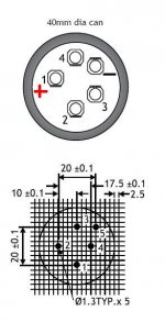
The picture below is of the newer BHC pin configuration. It is quite similar but will not fit!!!!!! Just a couple of mm out of alignment.
The originals have the +ve and -ve pins ~22.5 mm apart.
I am looking for.......
15000 - 22000uF
50V or more
max height ~67 mm and 40 mm diameter or less.
The + and - terminals are not centered with the -ve being close to the edge so I would prefer 35mm diameter if possible.
5 pin caps do not fit.
3 pin caps do not fit.
I cannot find 22.5mm 2 pin caps that are short enough to fit inside the case.
Aaaaaaaaaaaaaaaargh!!!!!!!!!!!!!!!!!!!!!!!
Attachments
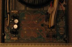
Can you post a picture of the pcb copper where these caps should fit in?
From all the supplies I have seen until now, you should have quite certainly have two points you can drill, according to the pin positions of the caps you have (Panasonic, etc.). Just do that and solder the new caps.
Forget about the BHC caps.
From all the supplies I have seen until now, you should have quite certainly have two points you can drill, according to the pin positions of the caps you have (Panasonic, etc.). Just do that and solder the new caps.
Forget about the BHC caps.
carlmart said:Can you post a picture of the pcb copper where these caps should fit in?
From all the supplies I have seen until now, you should have quite certainly have two points you can drill, according to the pin positions of the caps you have (Panasonic, etc.). Just do that and solder the new caps.
Forget about the BHC caps.
Hi Carl, thanks for the advice.
I have already posted some pictures here (post 25 etc.):
http://www.diyaudio.com/forums/attachment.php?s=&postid=1118466&stamp=1169998881
You can see from the photo that it will not be easy to fit four 10 mm pitch caps on those rails. It is hard to find 22.5mm pitch caps. It is made extra difficult because the +ve and -ve terminals were not in the center of the original.
I don't want to mess this up.
I will take a picture from the top with the caps removed.
Cheers,
Martin.
P.S. Anyone know where to get reasonably cheap but good quality caps? I have checked RS, Farnell, CPC, Hifi collective and others.
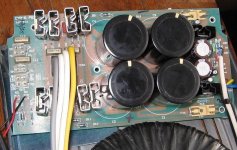
I finally plucked up the courage to drill the board and have also scraped away the insulation (solder mask?) from the underside ready for new caps. It is ready now for 2 pin, 10mm pitch, 35mm max Diameter caps. I wish that I had just done this sooner but nerves got the better of me and clouded my judgement.
Thanks Carl for your advice. I have forgotten about the BHC caps and all the multipin types.
The final fitting will not be perfectly symmetrical but I can make it work. Maybe you can see why I had the problems...........
Each white circle is 40mm diameter.
Thanks Carl for your advice.
I have forgotten about the BHC caps and all the multipin types. The final fitting will not be perfectly symmetrical but I can make it work. Maybe you can see why I had the problems...........
Each white circle is 40mm diameter.
Attachments
Sonusthree said:My next problem is:
Can I safely change the caps from 15000uF caps to 22000uF?
I think that it may be best to ask in the power supply forum though.
What power supply forum are you talking about? Is there any that I don't know about?
There shouldn't be much of a problem for changing from 15000 onto 22000uF. The strain will mostly be on the bridge/diodes and the power switch.
One thing you could improve on, which many people are doing now, is replacing the bridge/diodes for new types. Like MUR860. They are ultrafast TO220 types. They will certainly stand the switch-on higher current from the new caps.
Are those diodes on the right the power amp's? If they are then it's very easy to replace them. Many people have reported audio improvements after doing so.
Same thing for the low current diodes for the preamp. Also change the preamp's supply caps, which should be old too.
And that's it. Good luck!
carlmart said:What power supply forum are you talking about? Is there any that I don't know about?
http://www.diyaudio.com/forums/forumdisplay.php?s=&forumid=67
Hi Sonus,
keep in mind that the PSX electrolytics are working at relatively low frequency. Mostly due to local decoupling/bypassing in the amp and the long leads from PSX to One/Two.
With this info it is easy to make a decision to extend the 2pin connections across to the relevant PCB tracks with <10mm long insulated 0.6mm solid core copper wire. Problem solved. Not as neat but perfectly functional and no deterioration in audio quality.
Go for 22mF if they fit. You still have the transformer and PCB track resistances to reduce the size of the peak currents at start up.
+-44mF for two 8ohm channels in parallel gives my ideal PSU capability (RC=176mS) for good bass. But, set the input high pass filter to <=90mS to match this.
You can then experiment with bigger film (foil or metalised, PP or PS) decoupling at the amp to bring up the mid and treble to your liking.
Hi everyone,
Thanks to you all for the help you have given me. I was finding it very hard to select the right components and your advice gave me the confidence to reach for the drill.
Just recapped the PSX today.
The new 22mF caps required new holes to be drilled. They are now arranged slightly asymmetrically but this is no problem. A few very short wire links were needed.
Wire links were also added to mount the replacement diodes upon. This seems quite robust.
Thanks for the advice on diodes etc. I think my new ones should be up to the job. The power switch is rated at 10Amps. I can relax now.
Initial listening impressions are very good. I won't go into too much detail without further listening but the most striking thing is the improved low frequency transient response. The 'B' of the Bass is Back! I haven't heard any deterioration in the mids and highs when compared to the recently recapped Cyrus (2 without PSX).
I'll update my findings after a good listening session and thanks once again to everyone for all your help.
Cheers,
Martin.
Thanks to you all for the help you have given me. I was finding it very hard to select the right components and your advice gave me the confidence to reach for the drill.
Just recapped the PSX today.
- Swapped 4 X 15000uF for 4 X 22000uF Mundorf M-Lytic.
Changed 8 large diodes to BYW80-200 20 Amp 35nS with heatsinks. (TO-220).
Cleaned existing low voltage reg heatsinks and used (silver) thermal paste.
Replaced all caps in low voltage section.
The new 22mF caps required new holes to be drilled. They are now arranged slightly asymmetrically but this is no problem. A few very short wire links were needed.
Wire links were also added to mount the replacement diodes upon. This seems quite robust.
Thanks for the advice on diodes etc. I think my new ones should be up to the job. The power switch is rated at 10Amps. I can relax now.
Initial listening impressions are very good. I won't go into too much detail without further listening but the most striking thing is the improved low frequency transient response. The 'B' of the Bass is Back! I haven't heard any deterioration in the mids and highs when compared to the recently recapped Cyrus (2 without PSX).
I'll update my findings after a good listening session and thanks once again to everyone for all your help.
Cheers,
Martin.
Attachments
Well done!
Now your initial findings are completely at odds with a parallel thread where some quite experienced builders insist that the PSU capacitance CANNOT improve the bass response, all be it, anywhere below a maximum power test measurement. I think they reluctantly accept that PSU capacitance may affect the maximum power response.
You, as expected, have already found at least a difference in bass if not necessarily response.
I await you fuller findings. I want to stick it in their face and say "look independant evidence", because they will not accept my word for it, no matter how often or differently I argue the case.
Hi,
My equipment is probably a good test rig:
An amplifier that was designed to supply high currents to 8 Ohm speakers,
Reasonably large, powerful & sensitive 'closed box' speakers with 6 Ohms impedance.
In the past three weeks I have heard:
Cyrus PSX powered Cyrus 2 (original caps +-30mF)
Cyrus 2 (Original +-10mF)
Cyrus 2 with new +- 12mF
Cyrus PSX powered Cyrus 2 with new +-22mF caps. (While awaiting uprated diodes)
Cyrus PSX powered Cyrus 2 with new +-44mF caps)
I could go into details but you could probably guess how each increase in capacitance changed things
The specs of the original caps are probably meaningless due to their age. I cannot, therefore, judge the difference between +-30mf and +-44mF. Shame really and probably the most interesting comparison. I cannot judge whether the point of diminishing returns was ~30mF.
I read here and I listen and I mess around with simple circuits and mods. That is the extent of my knowledge. This is only my opinion ...................................................................................
The increased capacitance has made more current available to the amp and speakers and which part of the frequency spectrum requires most current? I can now see that the low frequencies were being starved.
The increased capacitance has NOT changed the tonal balance of the amp very much but has allowed the L.F. content to be more 'solid' and to reach lower down without strain.
I have not, so far, heard a change for the worse in the mids and highs. This surprised me since everything I know has come from this forum. What I have heard is the mids sounding more effortless as if nothing is holding it back. I would guess that the rails are now modulating less but who knows?
I strongly believe that more capacitance is not just beneficial for L.F transients at high S.P.L's. I do not fully understand why.
A little more listening time is called for. I will then perhaps be more certain of my results .......................
P.S. Anyone want to test my old caps? I'd be very interested to know what state they're in.
Cheers,
Martin.
Good job and great findings.
Now to add a bit more to the cake, you may try some tips suggested in these two articles:
http://www.tnt-audio.com/clinica/ssps2_e.html
http://www.tnt-audio.com/clinica/ssps3_e.html
Now that the bass in your amp seems to be taken care of, the zobel/snubber suggested by Dejan Veselinovic may be an interesting trick to try to see if the mids and highs can be improved too.
To know more go here:
http://www.zero-distortion.com/downlaod/glavna.htm
Then download the two zipped files on "Designing your own power supply". Open them and pay attention to tweaking the RC network.
It may be a good way to finish your job.
Carlos
Hi Carlos,
I'll start reading right away and I'll be back later with some questions, Thanks.
Cheers,
Martin.
I'll start reading right away and I'll be back later with some questions, Thanks.
Just one bridge (8 parallelled diodes). It would be nice to have two though!......did the Cyrus had separate bridges for +V and -V, or separate bridges per channel?
Cheers,
Martin.
Sonusthree said:Just one bridge (8 parallelled diodes). It would be nice to have two though!
I am not so sure you will need to parallel these new diodes.
The ideal thing would be if you could find a way to split the bridges as is suggested by Veselinovic. But for that you would have to cut the copper traces. IMHO it would be worth it though.
The other thing you could do is to replace those parallel diodes with RC snubbers. This is an arguable mod, though. I have read people saying things for and against it. I have only tried parallel caps, and they didn't seem to make any difference.
One thing that did work for me was to separate the left/right supplies, starting at the transformer. But that may not be possible with the space you have. It could be, but you would have to build new pcbs. Just a thought.
Carlos
Hi,
I cannot recommend the dual rectifier and a pair of cascaded single polarity supplies.
The single rectifier works just as well in the tests I have carried out and I know from the trace layout on your PCB that the design has been optimised to get the best out of that single rectifier arrangement.
The dual rectifier will cost twice as many diodes and loses an extra 0.7V off each rail. There is absolutely no gain in hum susceptibility nor in buzz attenuation.
I cannot recommend the dual rectifier and a pair of cascaded single polarity supplies.
Well, it's not only recommended on those articles that I mentioned, as it's also recommended for "Gainclone" projects, in the Chip Amplifier forum. I mentioned that on another thread.
The dual rectifier will cost twice as many diodes and loses an extra 0.7V off each rail. There is absolutely no gain in hum susceptibility nor in buzz attenuation.
The only additional cost would be to cut the copper trace as it is now, because the number of diodes would be the same he is presently using.
Hi,
Im really just starting to study power supply theory at the moment and I'm in no great hurry to heavily mod the rectification beyond the current setup .......... for now.
What is the disadvantage of parallel pairs? I know that one will always conduct more than the other due to heating effects but I don't see that as a problem here. Is the problem that both diodes will conduct at slightly different times creating more noise and maybe R.F.I.? That's just my best guess but I'd love to know more.
I'm really interested in snubbers and bypassing but my Tannoy's suffer badly from sibilance so I don't think that I could be completely objective until I get this sorted out. Could someone suggest some arbitrary values just to test wether the sibilance lessens or other things change?
Trial and error would probably be a fruitless exercise 'til I can remedy the 'Tannoy honk'.
Kind regards,
Martin.
Im really just starting to study power supply theory at the moment and I'm in no great hurry to heavily mod the rectification beyond the current setup .......... for now.
richie00boy said:I wouldn't parallel the new diodes as they are man enough on their own, and parallel diodes is not a great idea really.
What is the disadvantage of parallel pairs? I know that one will always conduct more than the other due to heating effects but I don't see that as a problem here. Is the problem that both diodes will conduct at slightly different times creating more noise and maybe R.F.I.? That's just my best guess but I'd love to know more.
I'm really interested in snubbers and bypassing but my Tannoy's suffer badly from sibilance so I don't think that I could be completely objective until I get this sorted out. Could someone suggest some arbitrary values just to test wether the sibilance lessens or other things change?
Trial and error would probably be a fruitless exercise 'til I can remedy the 'Tannoy honk'.
Kind regards,
Martin.
- Home
- Amplifiers
- Solid State
- Cyrus PSX dead