Re: even thd cancellation
Ahhh, Jan's comment is what I wanted to hear more about! What is the level? For products that are "widely accepted" to sound good, are there any commonalities in the distortion spectra, etc.
Hmmmm, maybe I should back up a minute and ask if there are any "widely accepted" good sounding amps
I'm not really looking for the one "best" design that everyone can converge on. I'm looking for good, fundamentally sound, design tuning tips. I think you can skin that cat in a number of ways; each offers different trade offs you can take advantage of depending on your goals, objectives, and secret agenda")
mlloyd1
Ahhh, Jan's comment is what I wanted to hear more about! What is the level? For products that are "widely accepted" to sound good, are there any commonalities in the distortion spectra, etc.
Hmmmm, maybe I should back up a minute and ask if there are any "widely accepted" good sounding amps
I'm not really looking for the one "best" design that everyone can converge on. I'm looking for good, fundamentally sound, design tuning tips. I think you can skin that cat in a number of ways; each offers different trade offs you can take advantage of depending on your goals, objectives, and secret agenda
mlloyd1
janneman said:.... However, it all depends on the levels...The odd orders in the SE may still be larger than those of the push-pull, and even orders are also not good.
Jan Didden [/B]
I'm confident Jan is right. It all depends on the levels.
For the choices given, the single ended input and VAS followed by the Class A push pull output stage would be best. Of course this assumes all other factors equal, which in a complex machine they rarely are!
Dogmatic statements must be avoided. Another we read in this forum concerns global feedback. Unless you use global feedback around the entire amp, it is most unlikely you will get Zout low enough to comfortably drive a speaker, however. Split the feedback a la Charles Altmann, taking it from the drivers or voltage amplifier and not the output devices, and listen to the amp. It sounds strangely tube-like, with tubby bass, improved imaging and tragic loss of slam. There is much nonsense talked about negative global feedback (voltage); I say it's necessary, and it is merely a question of HOW and HOW MUCH is applied. One must choose a judicious mix of global and local feedback, and any degeneration required is best implemented - in my view (and nothing is more dangerous than one man's opinion) - at the diff pair rather than at the voltage amplifier.
There is an unfortunate tendency for most audio engineers to stare hard at the CRO during design and strive for symmetrical clip. All too often this provokes odd order harmonics - small magnitudes certainly but audible over a longish listening session. An asymmetric clip is nothing to be ashamed of as long as it does not severely limit collector efficiency. Such a clip is patently even order, looks very strange, but sounds warm in lowish quantities, say less than 0.2%. More than this robs resolution.
The sound is a product of design topology, components, and layout. A good layout has superior stability and requires less compensation, fostering good sonics. Layout is not something which can be slavishly created; it takes time, and many iterations. This is naturally expensive, and only an obsessive on a mission would do it. Short, uncomplicated paths into the voltage amp and around the diff pair and feedback networks are essential, and indeed this is stated time and again with the Gainclone discussed on this forum.
Many problems with resolution on SS amps are in fact short term, transient oscillation. During these events the feedback loop loses control of the amp, and while the amp is busying itself with bothersome housekeeping it not even glancing at its input. Naturally, this costs sonic detail.
I really don't think there is any easy way to design a SS amplifier. You just have to build the bloody thing and go through endless prototypes and listening tests until it's 'right'. And all too often the endpoint becomes a commercial decision. If you produce a good amp first ime, then you are either born lucky or 1 very smart person with truckloads of experience.
But who said we all want the destination? For those compulsive-obsessives who do this for a living, it's the jouney, man, the journey!!
Cheers,
Hugh
You Are Right AKSA>
I did this years ago on a Technics Power Amp. this was a nice starting block separate power supplys for each channel I think Thay call that dual mono. and real Big and coll Analog Power meters.
The Mods I first did just as perposed take the main feedback loop from the output to the VAS stage that was a cascoded common emitter. this was at the Input to the Predriver transistors. This really fattened up the bass like in Tube Gear at least old tube gear. the Midbass and bass were the most effected. But the Highs also smoothed out alot! Stability was improved as i could now connect my Koss ESP 9B Electrastatic headphones without the Amp Going in to full oscilation. with this mod This amp drove complex loads alot better than it did Prior. I later also disalbeled the Output current Limit and got again Dramiticaly improved performance into evean reasonable loads like the JBL 4311. I sugest anyone try this. However in the end i reconnected it in a Multi-Loop configuation and this gave a blend of boath worlds and was what i used in my own Amp design but based upon !Gasp! Full complimentry Leach style in cluding a non frequency selective multi-Loop feedback Network that Professor leach included. Leaches network was frequency selective and i did not like that.
Another Point I agree upon is that it takes alot of time to obtain the Sonic best from any giver Topology. i spent years and several prototypes on the above Leached based design. i may have a schematic somewhare ill scan and post when i find it
Indeed we are straying far from the original intent, however, the argument that started this exchange was...what sounded better, a current source for biasing a LTP input stage, or a vanilla resistor.
Part of my motivation is to attempt to remove the small amount of DC offset I get at the amp output. It is a mere 45mV or so, but the amp is a testbed for ideas anyway, so I was hoping to see how adding a current source in place of a resistor would affect sound quality and the DC offset at the amp output.
Daniel Rosa has agreed to send me a few of his ultra-cool little PC boards, which I will use to add a current source to the input stage. The nifty thing here is..I have two identical amps that I can A/B to listen for differences after adding the current sources to one of them. It should be an interesting experiment...
Back on Track I think The CRD will lower your DC offset. At least that is what i have encountered most of the Time On manny different amps. the one time it did not produce better DC offset was a complimentery Diff amp Stage pair. on normal single Diff Amp. Always has lowered DC Offset.
I myself Perfer Current sourced Diff Amps and resistor load for the Vas stage. Gess as Mr Pass Put it it Depends.
I myself Perfer Current sourced Diff Amps and resistor load for the Vas stage. Gess as Mr Pass Put it it Depends.
Great experiment, I'm keen to know your results.I have two identical amps that I can A/B
If I were you I'd A/B the two "identical" amps first, before modification, to check whether they sound indistinguishable or not.
Jeff:
This is a good point. I had mentioned this concern to Jocko during an email exchange a while back. My current amp is Borbely Servo 50 with the complementary symmetric JFET input stage. The JFETs are matched for Idss, but I did not match them for anything else. When I was prototyping this design, I found I could have N and P jfets with matched Idss but the gains would be different: the N channel diff pair would have a gain of 10 v/v for example while the P channel pair would have a gain of 8V/V Yes, you can reduce (maybe "alter" is a better word?) the impact with source degeneration. But this difference in gain can't be good if you're trying to get cancellation! With a bipolar front end, this problem is a little easier (and cheaper!) to manage.
Good discussion all. Keep it coming
mlloyd1
This is a good point. I had mentioned this concern to Jocko during an email exchange a while back. My current amp is Borbely Servo 50 with the complementary symmetric JFET input stage. The JFETs are matched for Idss, but I did not match them for anything else. When I was prototyping this design, I found I could have N and P jfets with matched Idss but the gains would be different: the N channel diff pair would have a gain of 10 v/v for example while the P channel pair would have a gain of 8V/V
Yes, you can reduce (maybe "alter" is a better word?) the impact with source degeneration. But this difference in gain can't be good if you're trying to get cancellation! With a bipolar front end, this problem is a little easier (and cheaper!) to manage. Good discussion all. Keep it coming
mlloyd1
Jeff R said:Michael,
....I will throw out one complication that I can think of - in the complementary symmetry design, how well are the transistors in the input stage matched? ....
They've been A/B'd many times, and sound nearly identical with the exception of a bit better bass extension on one due to a minor VAS stage modification. Subtle, but there. I know the way both of these amps sound very well after listening to them for over 25 years, so any changes will be obvious to me.traderbam said:
Great experiment, I'm keen to know your results.
If I were you I'd A/B the two "identical" amps first, before modification, to check whether they sound indistinguishable or not.
ppl, I am hoping that the current source does the job and reduces the DC offset. It should.
On any SS PP amp with a diff pair up front you can trim offset by merely changing stage current through the output stage.
If the bias path for both transistors of the diff pair are the same resistance, then this method will also ensure that the diff pair is well balanced. Perfect balance is difficult to obtain, and calls for identical Vbe AND beta on each Diff pair device, but this approach is actually superior to a current mirror, which routinely fails to deliver perfect current balance by design.
A simple resistor, my preferred feed arrangement, can be very simply trimmed with - drum roll - a 'trimmmer'!
Cheers,
Hugh
On a side note, I am leery of any design that requires parts to be matched in order to achieve your goal. Designing for a specific part, and requiring that it be matched with another is poor practice (with the possible exception of output devices).Jeff R said:I will throw out one complication that I can think of - in the complementary symmetry design, how well are the transistors in the input stage matched?
mlloyd1 said:My current amp is Borbely Servo 50 with the complementary symmetric JFET input stage. The JFETs are matched for Idss, but I did not match them for anything else. When I was prototyping this design, I found I could have N and P jfets with matched Idss but the gains would be different: the N channel diff pair would have a gain of 10 v/v for example while the P channel pair would have a gain of 8V/V
Hi Michael,
It isn't easier matching BJT's. I was trying to do such matching for my Leach Amp and the lowest beta's for the NPNs were higher than the highest beta's for the PNPs.
I am not so sure how audible this mismatch is, however. Here is my line of reasoning. With emitter degeneration, and assumming that the gain mismatch between the NPN and PNP diff amp stages is not excessively different and that that the gain-setting resistors are also closely matched, then the level of the signals from each stage which drives its corresponding VAS transistor will be pretty much equal, but opposite in phase. Thus, second order distortion cancellation should be pretty much complete. I actually see a bigger problem with mismatches of the gain-setting resistors than I do with beta mismatches. (Vbe mismatches could be another story, though.) I mean, if the beta of the NPN stage is 20% higher than the PNP stage, with local feedback and with perfectly matched resistors, the amplitude of the output signals should be very, very close from each stage, at least at audio frequencies. Now, if the resistors are mismatched by even .5%, this would cause the amplitudes between the two sections to vary more than would the beta mismatch and would decrease the effectiveness of second order harmonic cancellation. .
So, is matching of the gain setting resistors in a complementary-symmetry design at least as important as beta matching?
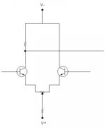
Some more info about diff amps
For bipolars the small-signal transconductance (ic/vbe) is pretty close to 40*Ic and this is independent of beta. So provided the collector currents are matched, the transconductances of npns and pnps will be pretty much identical. It is important to make the dynamic Ic much smaller than the dc Ic to minimize distortion. The different betas will affect the differential impedance seen between the bases.
Ex1: two BJTs with beta of 200 and Ic set to 1mA, no emitter resistors.
The transconductance of each BJT will be 40*0.001=0.04S.
The differential transconductance of the LTP will be 0.02S (since the transistors are effectively in series). This means that for every volt of difference between bases, each collector will change current by 20mA.
Input R of each BJT will be beta/gm = 200/0.04 = 5000 ohms. The differential R will be 10kohms.
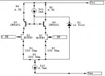
For JFETs the transconductance changes much less with Id. It is a much more linear characteristic. But the problem is that the transconductance value is device dependent and not matched by matching Id - so careful selection is needed or a dual device like a 2N3958 (where the gm ratio can still be as high as 1.18). Also, JFETs tend to have lower gms, often <0.005S. Another consideration is that a JFETs gm is more sensitive to changes in Vds than a BJTs gm to changes in Vce.
Ex2: two JFETs, gm=3mS, Id=1mA, no source resistors
Differential transconductance = 1.5mS. For every volt of difference between gates each drain current will change by 1.5mA.
Input R will be meg-ohms, so not an issue.
The other consideration is capacitance. JFETs have higher capacitances than BJTs, significantly so.
JFETs are going to give a more linear behaviour if the %change of output current of the LTP is high. This is typically the case with no or low feedback designs. With high feedback designs the change in current tends to be very small and so the BJT option is better. The BJT option is always easier for matching. The capacitance difference and particularly the ease of matching capacitance is more critical to high feedback/wide bandwidth designs.
For bipolars the small-signal transconductance (ic/vbe) is pretty close to 40*Ic and this is independent of beta. So provided the collector currents are matched, the transconductances of npns and pnps will be pretty much identical. It is important to make the dynamic Ic much smaller than the dc Ic to minimize distortion. The different betas will affect the differential impedance seen between the bases.
Ex1: two BJTs with beta of 200 and Ic set to 1mA, no emitter resistors.
The transconductance of each BJT will be 40*0.001=0.04S.
The differential transconductance of the LTP will be 0.02S (since the transistors are effectively in series). This means that for every volt of difference between bases, each collector will change current by 20mA.
Input R of each BJT will be beta/gm = 200/0.04 = 5000 ohms. The differential R will be 10kohms.
For JFETs the transconductance changes much less with Id. It is a much more linear characteristic. But the problem is that the transconductance value is device dependent and not matched by matching Id - so careful selection is needed or a dual device like a 2N3958 (where the gm ratio can still be as high as 1.18). Also, JFETs tend to have lower gms, often <0.005S. Another consideration is that a JFETs gm is more sensitive to changes in Vds than a BJTs gm to changes in Vce.
Ex2: two JFETs, gm=3mS, Id=1mA, no source resistors
Differential transconductance = 1.5mS. For every volt of difference between gates each drain current will change by 1.5mA.
Input R will be meg-ohms, so not an issue.
The other consideration is capacitance. JFETs have higher capacitances than BJTs, significantly so.
JFETs are going to give a more linear behaviour if the %change of output current of the LTP is high. This is typically the case with no or low feedback designs. With high feedback designs the change in current tends to be very small and so the BJT option is better. The BJT option is always easier for matching. The capacitance difference and particularly the ease of matching capacitance is more critical to high feedback/wide bandwidth designs.
Hi folks,
Very interesting this topic and I have a question about the even harmonic cancellation.
As mlloyd, I made some amps using complementary symmetric input stage like Borbely's designs and I liked very much the results.
My point is if I have a non-symmetrical design, for shure I'll have more even order harmonics present, and I'll have odd order harmonics too. In a theoretical experience, if I modify this stage to a symmetrical one, maintaning the level of odd harmonics and reducing the even ones, will it sounds worse? Or, in this case, since I changed the stage the level of odd harmonics will be changed?
Or, in other way, do you think the composition of the harmonics is relevant, in this case?
Tks in advance for your thoughts.
- Status
- This old topic is closed. If you want to reopen this topic, contact a moderator using the "Report Post" button.
- Home
- Amplifiers
- Solid State
- Current Regulator Diodes (CRD) - Why Seen So Seldom?