
Hi Jam,
Thanks for your response; yes, I have tried doubling the current, and yes, you have a point, but I still found the resistor better in the doubled role as well.
However, this is subjective, people differ in their judgements, and that's cool.........
I do like the simplicity, even if one pays with lower PSRR.
Nelson, thank you, you demonstrate that context in electronics is at least as important as it is in written English.......
Cheers,
Hugh
Hugh,
At the risk of angering the Master have you tried attaching the resistor (tail of the differential) to a much higher supply voltage say twice B+ (pnp differential).
I tried it once and it seemed to perform better (more reach?) till I turned to the dark side and started using current sources.
Regards,
Jam
OK, teach a newbie how to build a current source (simple one with a JFET, not much room here). I have a PNP input pair (2SA1085) running with a +14V / -44V supplys. Total tail current is now at about 1.6mA.jam said:Hugh,
At the risk of angering the Master have you tried attaching the resistor (tail of the differential) to a much higher supply voltage say twice B+ (pnp differential).
I tried it once and it seemed to perform better (more reach?) till I turned to the dark side and started using current sources.
Regards,
Jam
...or if anyone knows where to get about half a dozen CR106's....

You can get
1N5298
CR200, 300, 330, 470
J500, 503, 505, 507, 508, 510, 511
From Farnell Electronics www.farnell.com/uk
They will export, email them at: export@farnell.com
1N5298
CR200, 300, 330, 470
J500, 503, 505, 507, 508, 510, 511
From Farnell Electronics www.farnell.com/uk
They will export, email them at: export@farnell.com
Echo Wars,
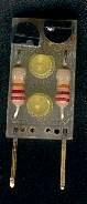
Wouldn't a two pin daughter board be better? The image (I believe) I attached uses a complementary pair and is self regulating. The dropout is about 2Vled. I'm also working on one for a single/cascode FET with or without the capacitance suppressing resistor, it's a bit smaller. E-mail your address and I'll send you a few.
Dan
Attachments
AKSA said:
This clearly is second harmonic distortion, caused by the asymmetric delivery of current from a simple resistor. This approach is only viable on a single diff input stage, since a fully complementary beast induces identical distortion profiles at both ends of the waveform, thus qualifying as odd order, and nasty.
Forgive me as I am not overly familiar with the AKSA design, but does this mean:
1. Fully complementary symmetric designs should use CCS's rather than resistors for best results?
2. Fully complementary symmetric designs have more third order distortion regardless and are thus less desirable despite the theoritical advantages?
Thanks for any insights,
Jeff
Re: Use the Source, Luke
The Aleph amplifiers were (are) an excellent case in point. By replacing the resistive loading off the input diff pairs (390 ohm as I recall) with constant current sources, we were able to drop the distortion numbers a lot, as this generated more open loop gain usable for feedback. We didn't like the sound as much, however, and elected to stay with the resistor.traderbam said:[BI agree in the sense that you may choose to introduce distortion in one place in order to compensate for distortion in another. If you don't want to hear your LTP then use a CCS. [/B]
Hi Jeff,
No forgiveness required, your observations are correct........
1. Fully complementary symmetric designs should use CCS's rather than resistors for best results?
I believe so.
2. Fully complementary symmetric designs have more third order distortion regardless and are thus less desirable despite the theoritical advantages?
Ditto.
This is audio heresy. Handle with care; watch crazy people with stakes very carefully......
Cheers,
Hugh
Thanks, Hugh. I do understand that people may disagree!
I have spent my life I (it seems) studying the Leach design and am quite familiar with, and I know he said he used resistors for the simple fact that it added a lot of complexity to the PCB and he felt it sounded fine with just the resistors. I have been aware that many dislike CCS's despite their theoritical advantages, but I had not before heard that CCS's may be good for fully complementary symmetric designs.
I am quite aware that the fully complementary symmetric designs theoritically cancel out all even order distortion, leaving primarily odd order distortion. I know odd order distortions sound worse than even order distortions, but it appears that the odd order distortions of the fully complementary symmetric design may be worse than the combined total distortion of the more conventional design.
Even so, we have all seen that low distortions of any kind does not translate into a great sounding amplifier. Alas, then, it appears that amplifier topology is only one a great many factors that make up great sound.
Thanks again,
Jeff
This has the potential to be a very interesting (or very dangerous  ) conversation.
Lets make this complex situation "unrealistically" simple so we can talk about it. I have four amplifier designs. No overall loop feedback (local per stage is OK). Semiconductors, bias points, impedances, frequency compensation, supply rails, etc. are chosen so that all front ends have identical (or as close as possible) BW, gain, etc. Same for the output stages.
1.single ended front end (eg. AKSA-like) + single ended class a output stage
2.single ended front end + push pull class a output stage
3.complementary symmetric front end (eg. Leach-like) + single ended class a output stage
4.complementary symmetric front end + push pull class a output stage
Which design (1,2,3,4) has lowest T.H.D. over the audio band?
How is the distortion spectra distributed across the audio bandwidth?
Which design (1,2,3,4) is more accurate?
Which design (1,2,3,4) has most "pleasing" distortion spectra distribution or which design (1,2,3,4) sounds the best TO YOU?
Well, what say you?")
mlloyd1
) conversation.Lets make this complex situation "unrealistically" simple so we can talk about it. I have four amplifier designs. No overall loop feedback (local per stage is OK). Semiconductors, bias points, impedances, frequency compensation, supply rails, etc. are chosen so that all front ends have identical (or as close as possible) BW, gain, etc. Same for the output stages.
1.single ended front end (eg. AKSA-like) + single ended class a output stage
2.single ended front end + push pull class a output stage
3.complementary symmetric front end (eg. Leach-like) + single ended class a output stage
4.complementary symmetric front end + push pull class a output stage
Which design (1,2,3,4) has lowest T.H.D. over the audio band?
How is the distortion spectra distributed across the audio bandwidth?
Which design (1,2,3,4) is more accurate?
Which design (1,2,3,4) has most "pleasing" distortion spectra distribution or which design (1,2,3,4) sounds the best TO YOU?
Well, what say you?
mlloyd1
Jeff R said:Thanks, Hugh. I do understand that people may disagree!
... fully complementary symmetric designs ... cancel out all even order distortion ... odd order distortions sound worse than even order distortions, ... odd order distortions of the fully complementary symmetric design may be worse than the combined total distortion of the more conventional design...
Jeff [/B]
Re: Amplifier Model
Hi Elso,
Could be both, but I wrote this with Power Amps in mind.
I also forgot to add the constraint that we won't operate near clipping. Yeah, I know that's unrealistic, but we have to stop somewhere. Beside, most listening that I do is nowhere near clipping for any of my amps. No, my amps are not monsters; I'm married, so I don't shake the dust out of the speakers until the women are out of the house (usually shopping) 
mlloyd1
Hi Elso,
Could be both, but I wrote this with Power Amps in mind.
I also forgot to add the constraint that we won't operate near clipping. Yeah, I know that's unrealistic, but we have to stop somewhere.
Beside, most listening that I do is nowhere near clipping for any of my amps. No, my amps are not monsters; I'm married, so I don't shake the dust out of the speakers until the women are out of the house (usually shopping) mlloyd1
Elso Kwak said:Hi Michael,
Is this a example of a preamp (line amp) or a poweramplifier?
Michael,
If this was easy and had definitive answers, we would all be using that "best" design!
I will throw out one complication that I can think of - in the complementary symmetry design, how well are the transistors in the input stage matched? If perfectly match, I think that form of design would offer the best "spec'd" performance. But, since you can never achieve perfect matching, the actual performance will never match the theoritical performance.
I am not smart enough to say much more, but I hope we get some good comments.
I am quite aware that the fully complementary symmetric designs theoritically cancel out all even order distortion
I'm curious. This concept of cancelling distortion comes up now and again, usually in the context of push-pull configurations. What does it mean? For example, does it mean even harmonics are reduced when observed on a spectrum analyzer?
even thd cancellation
It means that in push-pull amps both halves of the sine wave signal (pos half & neg half) distort the same way, for instance both halves get extra "pointy"near the top, or get extra "flat"near the top. If you subtract the original sine wave from this distorted signal, what rermains are odd order harmonics to the original one.
In a SE amp, both sine wave halves do not distort the same way. You can have, say, the pos half that gets extra "pointy"and the neg half that gets extra "flat". Subtracting the original gives you in this case even order harmonics.
Now, it is said that odd order harmonics are more objectionable than even order ones. Therefor you would say that if the even order ones are missing in the push-pull case, and the odd orders are there. That would be audibly worse. However, it all depends on the levels. You cannot say that an SE amp is better sounding because it has predominantly even order harmonics. The odd orders in the SE may still be larger than those of the push-pull, and even orders are also not good.
Jan Didden
- Status
- This old topic is closed. If you want to reopen this topic, contact a moderator using the "Report Post" button.
- Home
- Amplifiers
- Solid State
- Current Regulator Diodes (CRD) - Why Seen So Seldom?