lumanauw said:Interesting possibility. Just how to put differential to sense RE (0.22ohm for 10mA) between Transistor's emitor (in EF) and output line (to feel the voltage at 0.22ohm with 10mA)?
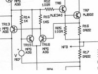
Are you thinking of something like that?
Attachments
Daniel,
You must use two LTPs; NPN for positive rail, PNP for negative rail.
Both are fed from CCS; NPN LTP from the negative rail, PNP from the positive rail.
Right side bases of the LTP connect to the OP Device side of each emitter sense resistor (0R22), and left side bases connect to a voltage reference, a resistor of a few ohms driven from secondary CCSs supported from each rail.
You then use a large resistor on the correcting transistor's collector to kick start the driver base at each side.
This is all conjecture. I've not built anything like this. It might work.......
Have you considered Blomley's 1970 design? It should be somewhere on the web, and uses small signal transistors to divide the signal for each output half, whilst ensuring the output devices are always on, but in Class B.
Cheers,
Hugh
Cheers,
Hugh
yes ,i'm too. Lumanaw! What's time is it ?lumanauw said:The power amp by Peter Blomley is talked everywhere, but I cannot see the sch. Does anyone knows where to see it?

Now forum is sad because there are not much member
Hi, GM,
Thanks for the drawing. It doesnt use differential, so it cannot maintain DC offset (output using cap)?
You have seen more schematic than I have all this time Do you have other SCH that doesnt turn-off in the final stage (in class AB, offcourse). This Blomley is hard to understand, and using cap in final output.
GM, the issue that you mentioned, the reactive speaker kicks back to the amp, is it got back to the amp via feedback (directly to differential) or ramping from final stage to VAS to differential (since if we use bipolars, emitors/collectors are always connected to base)? Is this also happens in pure classA (with feedback)?
Thanks for the drawing. It doesnt use differential, so it cannot maintain DC offset (output using cap)?
You have seen more schematic than I have all this time
Do you have other SCH that doesnt turn-off in the final stage (in class AB, offcourse). This Blomley is hard to understand, and using cap in final output. GM, the issue that you mentioned, the reactive speaker kicks back to the amp, is it got back to the amp via feedback (directly to differential) or ramping from final stage to VAS to differential (since if we use bipolars, emitors/collectors are always connected to base)? Is this also happens in pure classA (with feedback)?
Steven said:Hans Hartsuiker once published another Blomley type amplifier with an opamp input iirc. It was in the Wireless World say 5-10 years ago, maybe more.
I heard that one in 1984; it was actually very good. He published it much later.
I should have a copy somewhere....
Steven
There is one similar by Ian Hegglun, Electronics World, March 1995. The same author, September 1995.
- Status
- This old topic is closed. If you want to reopen this topic, contact a moderator using the "Report Post" button.
- Home
- Amplifiers
- Solid State
- Crossover distortion