Joseph K said:So, the leads are NOT displaced by all the length necessary to reach that diameter - instead they are displaced only by the ~ space between the leads! [exactly the length of the half circumference of a roll with the lead space diameter]
[This all because the first lead is not connected to one end of the foil - but are connected with only that sligth shift - so the solenoidal currents are almost totally symmetrical for the ~full foil length, and so they cancel]
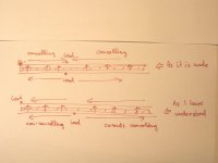
In the sketch I have signalled with only one line the full cap sandwitch structure - foil - dielectric - foil. I think this way it can be seen better.
Notice that in this way each of the leads are touching from a different side. One more thing is necessary: the opposite side foils should be displaced [shifted along the dielectric] by this small length described above.
So the resulting stray inductance is equal to this half - circumference, that is, ~ the lead distance. This is why the catalogs mention that ESL is ~ equal to the distance covered by the leads!
Ciao, George
I am confused by your confusion..

My description of how a jelly roll capacitor is made was intended to show how changes in where the wires were attached would affect the solenoidal inductance of the unit.
My descriptions of how the inductance would interact externally as well as internally were provided to allow one to test the extent of the effect for any capacitor.
As well, it provided a method of increasing the resonant frequency of an axial capacitor by neutralizing all the bulk external magnetic field associated with the current which travels from one end of the capacitor to the other by confining it using the return current in the way a coaxial construct does this.
In the old days before smps, capacitor esl was not of much significant, so it was possible to be very sloppy with the lead placement. Nowadays, it is easier to build the capacitors as you have witnessed to accomodate lower esl. What is unknown, is if the 4cmc radial capacitor I pasted the datasheet to suffers it's reduction of capacitance as a result of solenoidal forced dielectric current starvation, or if it is a chemistry based effect. Measuring the external solenoidal field of this particular capacitor vs frequency would most likely answer the solenoid question.
I very much enjoyed your test setup and the work you shared with us.. In the future, I would enjoy very much having you, or anyone else, use that exact fixture to test some of my current viewing resistor constructs, as I wish to test power amplifier outputs accurately in amplitude and phase out to approximately 10 to 100 nanoseconds, and current cvr's and loads are incapable of doing so.
My goal is to measure in the inverse bandwidth of 1 microsecond into 4 and 8 ohm power loads, and this requires some rather interesting technology..
Cheers, John
My apologies for not making myself clear...I will try better in the future..
Extreme_Boky said:Nice pics.
You should try pure silver ribbons in place of those wire links!!!
Extreme_Boky
The best one could hope for in substituting silver here is a small fraction of an inductive reactance at high frequencies, this is 50 nanohenries /12 inches or about 4 nanohenries, and this is the extreme case of all the current skinning to the wire surface. This refers to all the internal inductance of the wires, and the actual difference would be less than 1% of that. The change would result in about 40 picohenries difference per wire, which is inconsequential in this application.
Of more significance would be dropping the external inductance of those wires..splaying the wires in that fashion, while looking pretty, does not stop the external inductance. This by far, is the more fertile field to sow..
As it looks, the rail impedance has to be dropped locally at the point of use, and it required paying close attention to the fields around that wire set.
Cheers, John
Wait a minute, John!
Do not misunderstand me - I still think that Your explanation was perfectly logical, and - at least up to now - I was convinced of having understood it well [~]. What I wanted to say, is that I was disturbed by the fact that I was not able to measure the effect of it. [At least not in a due amount]. Though, the capacitor inspected by me seemed to be made exactly as You described. At least this was my claim.
Now, my post above just wanted to clarify, that the capacitor inspected by me - in a SuperFicial Way!! - was NOT made according to Your description, but includes an another little trick, which effectively reduces that effect described by You - to a much smaller level.
I think that Your description was appealing, and valid.
I don't think that You should be aware of all the actual little tricks applied by the manufacturers. So I did not mean to blame it on You!
I was actually correcting myself, I should have noticed that difference right at that time.
And for me, physics, Your description & reality are much closer now!
Here it is a short ugly sketch again to clarify it further: [or confuse, I don't know now..]
Attachments
Then, I am still in debt with You regarding the "coaxed" sore thumb axial capacitor - obviously I could not stop and finished in a more complete way the copper shield - well, the SRF point had shifted from ~1.1 MHz up to ~1.7MHz! That means the "virtual" ESL had decreased from 14nH to 6 nH! ANd I could still do it even better.. I would not be surprised if it would arrive at 3-4 nH - which is small stacked film [radial ] field..!!
So, hat's off!
So, hat's off!
And I think reducing the "virtual" ESL of such a phisically not small axial, good quality film or PIO capacitor is not a small achievement!
Not because the ESL by itself would cause heavy distortions and like.. but the ESL is a good indicator of the covered loop area, unnecessarily large, because of the not careful placement, exactly as You have told just now. And such a large loop area means too much possibility to pick up radiated EMI, and convert it for forever into the signal.
A perfect example is the tweaking of ClassD amplifiers by exchanging the input caps for film types. So I'm sure I will dress up my input Audyncaps on my AMP1 B exactly in this way..
And John, I would be interested in that measurement..
Ciao, George
Joseph K said:Here it is a short ugly sketch again to clarify it further: [or confuse, I don't know now..]
Your sketch is very good and correct.. Thank you for making it.
When you have made the srf as low as you can, then we will have an inductance to put on the graph I made. That will allow us to determine in a model, how much of the volume of the capacitor is carrying the current. Clearly it is not the wire diameter, and clearly it is not the capacitor outer diameter. While the effective current diameter will be somewhat geometry construction related, the information will allow us to make closer guesses for what the resultant inductance would be for different capacitors.
You're discussion about loop area is also very correct. A good radiator is also a good receiver.
Are you near Frascati?
Cheers, John
John,
Good! This way I'm happier..
Yes, I will report back - will see how close it is now.
Frascati - yes. ~100km, You get on the highway in Rome, and get out of it just in front of our institute. We aree right below the highest peak of the "Appenini Abruzzesi". This weekend Roma High End 2005...
Ciao, George
- Status
- This old topic is closed. If you want to reopen this topic, contact a moderator using the "Report Post" button.
- Home
- Source & Line
- Digital Source
- Copper foil around electrolytic capacitors?