
then the copper one -
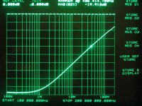
What you can see is everything equal. At the first sight. But look at the marker magnitude value, that is the measured attenuation value at always the same frequency - it's visible that with copper it goes "deeper", attenuates more, has less ESL. By 0.05dB..


But that's real and consistent!
Then, I will not waste more bandwith here, but this value for the alu hat on is -19.885 dB - exactly half way.
For me both theory & practice are satisfied - The change is there, but does not weight in in practice..
Faithfully Yours,
George
What you can see is everything equal. At the first sight. But look at the marker magnitude value, that is the measured attenuation value at always the same frequency - it's visible that with copper it goes "deeper", attenuates more, has less ESL. By 0.05dB..
But that's real and consistent!
Then, I will not waste more bandwith here, but this value for the alu hat on is -19.885 dB - exactly half way.
For me both theory & practice are satisfied - The change is there, but does not weight in in practice..
Faithfully Yours,
George
Attachments
Joseph K said:First of all, I have just really connected and re-measured that copper clad sore thumb [partially] suggested by jneutron [visiblehere]
The resonance frequency has changed from 1.1 to 1.291 MHz - I have never seen such a thing before! That means the "virtual" ESL has changed from 14nH to ~10nH! And the way it is executed is far from perfect - I will have to repeat it still better - will we arrive to nil?
No, it will not be possible to arrive at nil. That is why I asked you for the dimensions of the capacitor..
What you are doing is creating a coaxial "wire". All magnetic field outside the return shell has been removed by cancellation..what is left is the magnetic field between the inner "wire" and the outer shell.
That is defined by the equation:
L = mu/2 Pi * Ln (Ro/Ri).. What we do not know is the virtual Ri, that is the inner construct apparent diameter..to the first approximation, that should be about half the foil diameter.
Note:Ro is the inner diameter of the outer shell, Ri is the outer diameter of the inner conductor...mu is 4 pi 10e-7 henry/meter.
When you were first testing the axial, you had two parallel conductors..the inductance of that is:
L = .01016 * length * {2.303 * log(2*D/d)-(D/length)+(mu*.25)}
length is inches, D is wire spacing in inches, d is wire radius in inches, mu is relative permeability in this equation, so is 1...not absolute permeability..
Be aware that this equation is what I consider "unstable" for lengths which are small in comparison to the spacing..the D/length term blows up for very small length..
So, the best you can do is confine the magnetic field to within the outer shield, but no better.
Joseph K said:
In the meantime this thought kept on disturbing me - is it possible
that the alu can is source of my problems in demonstrating Jneutron's ideas?
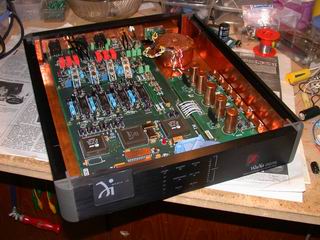
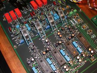
So I went on and scalped one capacitor, and measured the it's ESL
-bald skull
-alu hat
-copper hat
It is possible, and you are doing the correct thing to determine such.
Once you have tried the cap with and without a shield, unroll the construct to determine where the leads connect to the foils..If it is all the way to the inner end, then there is no solenoid to find.
Excellent work..thank you.
I will continue to look for the details of that Cornell-dublier capacitance test procedure..
Cheers, John
Jneutron,
Thanks for the fun!
Then, I was joking with the "Nil".
Yes, I have imagined exactly like that.
Furthermore, it would be still interesting to calculate - you gave me the right formula, but could You also fill in..?
The parameters are: For the polyprop cap: Length=27 mm D=14mm lead spacing was ~31mm
For the smaller green 1500nF MKT cap: length=20mm D=10mm actual lead spacing ~27 mm
So I don't have to dig out mu..
Ciao, George
Thanks for the fun!
Then, I was joking with the "Nil".
What you are doing is creating a coaxial "wire".
Yes, I have imagined exactly like that.
Furthermore, it would be still interesting to calculate - you gave me the right formula, but could You also fill in..?
The parameters are: For the polyprop cap: Length=27 mm D=14mm lead spacing was ~31mm
For the smaller green 1500nF MKT cap: length=20mm D=10mm actual lead spacing ~27 mm
So I don't have to dig out mu..
Ciao, George
Joseph K said:Jneutron,
Thanks for the fun!
Then, I was joking with the "Nil".
Ah, my apologies..

Joseph K said:
Furthermore, it would be still interesting to calculate - you gave me the right formula, but could You also fill in..?
The parameters are: For the polyprop cap: Length=27 mm D=14mm lead spacing was ~31mm
For the smaller green 1500nF MKT cap: length=20mm D=10mm actual lead spacing ~27 mm
So I don't have to dig out mu..
Ciao, George
What is also needed for the equations is the diameter of the leads. But, as the capacitor virtual inner lead is an unknown, I will do calcs with a guess of 30 mils (.030 inches) for wire diameter..
The poly:
Modelled as a simple wire pair, .030 dia and spacing of .28 inches, the inductance for this cap is 39 nH. The use of .030 diameter wire is obviously too small, both for the return ground plane and the virtual capacitor diameter.. (as the wire diameter goes down, the inductance goes up..)
So, try .140 dia wire pair, zero spacing..this will be closer to the real thing...this produces an L of 11.69 nH for the capacitor.
This is actually a bit too low, but I cannot model an assymetrical system yet, but will eventually be able to do this when I make my magnetic field software integrate the stored energy of the field.. So, I will have to live with this approximation for now..oh well..
The poly as a coax...using inner 30 mil wire, the L is 17.99 nH...using .140 (half the cap size), the number is 4.17.
Clearly, the effective diameter of the capacitor current is between the two...by adjusting this to get 10 nH, the inner effective diameter is calculated to be .05 inches.
Gotta re-boot...my excel ss went nuts...gonna attach some graphs, but can't make it work..hold on..
John
Joseph K said:John,
seems to be good that I asked..
One question: a serious part of the field is filled with aluminium - should it not be taken into consideration as well?
In the meantime, as I have promised, I AM BACK!
Yes, it should. I cannot model that in my spreadsheet, nor in my vb field code. So I can only assume it's presence lowers the inductance by eddy mirroring..
We can, however, use measured coaxial inductance to create a virtual diameter.
Your picture...does it show both foils ending at the input leads?
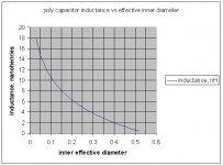
Here's a graph of the effective inductance..by using a close to perfect outer shield construct, we can find the effective diameter of the capacitor using this graph.
Ideally, the shield should be connected to the top lead all around, if you simply bend the wire over and solder, there will be asymmetrical current distribution along the shield, so there will be incomplete magnetic field cancellation. Simply connecting is not good enough, as we are not worried about the potential voltage, but only how the current travels.
Same at the bottom, where the shield is connected to the ground planes.
Cheers, John
Attachments
Joseph K said:And the fullstrip..
The strange thing about it is that it fits perfectly Your description, John!
But then why is it cancellating?
The foil displacement is ~15mm, the lead spacing is the usual 5mm / or 20 mil.
Ciao, George
By foil displacement, do you mean the distance the connections were apart along the strip?
If so, then how much of the total foil length of the capacitor is between the connections.. It would seem to be rather small, 5 percent or less of the total capacitor..
That far inside, and so little, there is no wonder the outer shell is of little significance.
We must find a capacitor which is constructed so as to make a very large external solenoidal field..in this way, we can perhaps find a capacitor where the use of copper foil outside can be significant??
Large computer grade capacitors which cannot afford such a hole in the middle comes to mind...
This has been a pleasure..thank you.
Cheers, John
John,
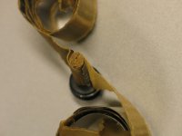
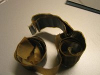
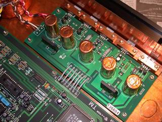
What You can see on the pic is that the input leads are attached at about the 5-10 % of the full roll, as You have described initially. In the first it's visible the still rolled up inner part between the leads, outer part unrolled.
In the last pic all unrolled, the inner part being ~ 2,5inches length of foil.
What you cannot see is that filthy smell..
Yes, You are right, at the "sore thumb" setup the connection was far from perfect, this is why I told I will try it again. practically I will have to reconstruct that small alu can // hat from copper, pinch it on top of the cap with the lead sticking out, then solder it on top and all around the bottom, as much as possible. At the bottom I did it, almost.
Ciao, George
Joseph K said:John,
What You can see on the pic is that the input leads are attached at about the 5-10 % of the full roll, as You have described initially. In the first it's visible the still rolled up inner part between the leads, outer part unrolled.
In the last pic all unrolled, the inner part being ~ 2,5inches length of foil.
What you cannot see is that filthy smell..
Yes, You are right, at the "sore thumb" setup the connection was far from perfect, this is why I told I will try it again. practically I will have to reconstruct that small alu can // hat from copper, pinch it on top of the cap with the lead sticking out, then solder it on top and all around the bottom, as much as possible. At the bottom I did it, almost.
Ciao, George
Thank you for the information..
I did not know about the smell..my apologies..
John

Dear all, but particularly John!
It has just kept on disturbing me, why the theory does not show up in the practical measurements, with radial capacitors?
Then I had a closer look at my own photos - at the time of taking them it was just that - taking them.. Thinking was never my strong side..
So I think to see a basic difference between the real cap structure and the description provided by John. John said:
Note the phrase: solder the bottom lead at the left end.. etc.
While, in the cap destroyed by me, it was like it's shown in my ugly sketch:
It has just kept on disturbing me, why the theory does not show up in the practical measurements, with radial capacitors?
Then I had a closer look at my own photos - at the time of taking them it was just that - taking them.. Thinking was never my strong side..
So I think to see a basic difference between the real cap structure and the description provided by John. John said:
So, to make a radial, do this: solder the bottom lead at the left end, but move the top lead a foot away and solder it there..this foot distance will cause the leads to be spaced apart by the thickness of the foil and dielectric times the number of turns you get with the first foot.
Note the phrase: solder the bottom lead at the left end.. etc.
While, in the cap destroyed by me, it was like it's shown in my ugly sketch:
Attachments
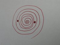
So, the leads are NOT displaced by all the length necessary to reach that diameter - instead they are displaced only by the ~ space between the leads! [exactly the length of the half circumference of a roll with the lead space diameter]
[This all because the first lead is not connected to one end of the foil - but are connected with only that sligth shift - so the solenoidal currents are almost totally symmetrical for the ~full foil length, and so they cancel]
In the sketch I have signalled with only one line the full cap sandwitch structure - foil - dielectric - foil. I think this way it can be seen better.
Notice that in this way each of the leads are touching from a different side. One more thing is necessary: the opposite side foils should be displaced [shifted along the dielectric] by this small length described above.
So the resulting stray inductance is equal to this half - circumference, that is, ~ the lead distance. This is why the catalogs mention that ESL is ~ equal to the distance covered by the leads!
Ciao, George
- Status
- This old topic is closed. If you want to reopen this topic, contact a moderator using the "Report Post" button.
- Home
- Source & Line
- Digital Source
- Copper foil around electrolytic capacitors?