anatech said:Hi John,
The dissipation factor does down the toilet first. Phase angles shift. Generally unpleasant stuff with a cap. Electrolytics without a DC bias do far worse things ( hysteresis). Ceramics suffer from the same thing.
Of course, the effects become more pronounced as the frequency increases. At any rate, I have doubts that the copper wrap truely helps in any meaningful way. But they take a great picture!
-Chris
Yes, all those effects are real.
If you doubt the copper as doing anything, test it..
Measure the effective capacitance of the lytic from 20 to 20K, with 50% voltage bias, both with and without a foil..
If the foil is really mirroring the solenoidal field thereby reducing the inductance of the cap, then there will be a measureable difference..poof....proof positive. Eliminates the possibility that it is just any paste effects. And, introduces the possibility of compensating those bad boys..THAT is a step forward..
Cheers, John
The reason for the copper foil wrap is to help reduce microphonics. Capacitors are notoriously microphonic, some larger film caps will even sound like low grade tweeters if you drive them with some current. Lead tape also works for vibration damping, though has environmental impacts rendering it not suitable for commercial production use.
hughmon said:The reason for the copper foil wrap is to help reduce microphonics. Capacitors are notoriously microphonic, some larger film caps will even sound like low grade tweeters if you drive them with some current. Lead tape also works for vibration damping, though has environmental impacts rendering it not suitable for commercial production use.
Have you anything to substantiate this correction around electrolytics? I believe milspec has some on this, but I haven't had to test passive devices for vibe resistance..
You make no distinction between current pinch, piezo, or magnetostriction with your statement of caps sounding like tweeters..you may not be discussing what occurs in lytics..
Cheers, John
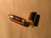
Maybe Pioneer don't want to pay for the boutique audio cap as Elna wrap the internal wingings with an isolated Aluminium foil, and Matsushita copper plate the outside of their cans, they also use a foam rubber in the centre of the capacitor winding.
Another bit of capacitor trivia:
Nichicon uses a 50 μm thick paper incorporating 70 wt.% of Manila hemp fiber and 30 wt.% of sheep wool fiber, or a 50 μm thick paper incorporating 90 wt.% of Manila hemp fiber and 10 wt.% of sheet wool fiber is used as the separator
The following might be of interest to some
JP9063891
Attachments
Can you explain? In what way has copper a certain sound? Have you tested other metals too so you really know the difference
I did try a lot of different materials in 2 different "shapes": solid cores and ribbons. I do not use litz / multi strand cables any more!! I experimented a lot, for 2-3 years.
A good friend of mine makes Power cables, interconnects, speaker cables, utilising these materials and shapes. He does it very successfully for 20+ years and his stuff is even recognised by Audiophile magazines. Mainly exports to USA. I got all the "raw" stuff from him. What he suggested regarding the sound of different materials / shapes - I figured out myself during those 2 years - exactly the same!!! I just did not want to believe, had to try for myself.
Once I learned how each material and shape sound, I learned to implement and match the same to transistor / digital gear, and to valve (and in particular - single ended valve/tube) gear. It is a fine tuning tool.
As are:
1. Power cables / Power distribution boxes
2. Interconnects / Speaker cables
listed in the order of affecting the sound most. Yes, the power cables are at the top!
Extreme_Boky
Jneutron,
What you say sounds really interesting. Could you be more explicit about a possible measurement with a network analyzer? That is, do you think such an effect shoud show up on it? Because I've tried something, but maybe not the right way?
I've used normal axial wound film caps. Do you think it has a basically different structure with respect to an electrolytic? For me it seemed to be logical, because of the missing alu shield. By the way, just the always present alu can should not have the same effect like the copper foil?
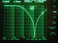
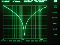
Will show more pics later. No change in the curves, with external copper foil on/off. I would think that SRF dip value, or Q, or RC time costant with the 50 ohm line impedance, something should show a bit of shift, at least?
best regards, george
What you say sounds really interesting. Could you be more explicit about a possible measurement with a network analyzer? That is, do you think such an effect shoud show up on it? Because I've tried something, but maybe not the right way?
I've used normal axial wound film caps. Do you think it has a basically different structure with respect to an electrolytic? For me it seemed to be logical, because of the missing alu shield. By the way, just the always present alu can should not have the same effect like the copper foil?
Will show more pics later. No change in the curves, with external copper foil on/off. I would think that SRF dip value, or Q, or RC time costant with the 50 ohm line impedance, something should show a bit of shift, at least?
best regards, george
Attachments
If you make a short on the output of an amplifier with a cap and the cap sings that is one thing.
The voltage induced in a cap by a soundwave is another.
Put an unconnected cap into a case and turn on music, measure the voltage induced in the cap and report here.
mV ? µV ? nV ?
Or better connect the cap to a DC voltage PSU and measure with AC coupled scope or analyzer.
The voltage induced in a cap by a soundwave is another.
Put an unconnected cap into a case and turn on music, measure the voltage induced in the cap and report here.
mV ? µV ? nV ?
Or better connect the cap to a DC voltage PSU and measure with AC coupled scope or analyzer.
That is, "invariant" is a bit strong expression, at these size / frequency values the slightest position change on the jig will introduce a slight gross-ESL shift. My statement above should sound like this " At first sight it seemed to be a bit less ESL, but then just by moving the cap by
1 mm I got back the initial values"
putting the foil on /off means moving the cap, unfortunately.
Ciao, George
1 mm I got back the initial values"
putting the foil on /off means moving the cap, unfortunately.
Ciao, George
 ))
))Joseph K said:Jneutron,
What you say sounds really interesting. Could you be more explicit about a possible measurement with a network analyzer? That is, do you think such an effect shoud show up on it? Because I've tried something, but maybe not the right way?
I've used normal axial wound film caps. Do you think it has a basically different structure with respect to an electrolytic? For me it seemed to be logical, because of the missing alu shield. By the way, just the always present alu can should not have the same effect like the copper foil?
Will show more pics later. No change in the curves, with external copper foil on/off. I would think that SRF dip value, or Q, or RC time costant with the 50 ohm line impedance, something should show a bit of shift, at least?
best regards, george
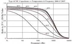
Axial caps are more likely to not have the issue..the leads are pulled out of the same location, so there is no net solenoidal current .
I'll attach a graph of what I'm talking about w/r to cap dropoff with frequency.
I'll also try to make a pic, but I fear I'll have to actually draw by hand (gasp) what I'm talking about and scan in at a later date. Here goes a description..for "current", think ac..
Take a pair of 5 foot long foils 2 inches wide..put a paper insulator between them. Attach both leads at the same end, on the left..
Current from the top lead goes from left to right in the top foil..along the length, the current goes through the insulator to the other foil..and then, the current travels in the bottom foil from right to left..exactly opposite the top foil..because they are so close together, they basically cancel each other out...the inductance is lowered by the foil pair proximity.
I have just described an axial capacitor..all you do now is roll this construct with another insulator, and you form a "jellyroll" cap.
Note that if you solder both leads on the same edge of this construct to make a radial capacitor, they will be very close together, and can short..
So, to make a radial, do this: solder the bottom lead at the left end, but move the top lead a foot away and solder it there..this foot distance will cause the leads to be spaced apart by the thickness of the foil and dielectric times the number of turns you get with the first foot.
Now look at the current..the top foil, current will travel both ways in the foil..to the right, it will still be cancelled by the current of the bottom foil...but, to the left, something different happens..
Current within the top foil heading to the left is going the same direction as the current in the bottom foil..so any current that goes through the dielectric will also head left...this does not cancel opposing currents..when this portion of the jellyroll is rolled up, the solenoidal inductance will add up..in the limit, if the top lead is all the way to the right, this construct will have the solenoidal magnetic field of an inductor with the same number of turns.
Depending on the geometry of the radial capacitor, this solenoidal field will be measureable outside the can.
I just finished testing a solenoidal magnet, and when we put an aluminum shield around the solenoidal windings, the 100 hz inductance dropped..making us scramble to model it magnetically with the shield eddy currents included, to show that it was by design and not a turn to turn short. (the magnet is a superconducting DC application, so we are not concerned with it's 100 hz inductance, we just use that for production quality tests. Major changes in the inductance is our indication that something went wrong in the production process.)
By repeating this capacitance vs freq measurement, you should be able to see if any capacitor is constructed to produce this effect. If the copper shield does do what I am claiming, it will be easily verifiable by measurement..note that the electric field within the cap should not in any way react with the copper outside the lytic..
Oh, almost forgot..an inductor that is made with wide ribbon will tend to exhibit skin effect by forcing the current towards the foil edges..when this happens in a capacitor, the center of the construct will begin to starve the dielectric..as no current will be there to go through the dielectric..if you find a solenoidal magnetic field outside a capacitor, there ya go..
Cheers, John
Attachments
Wov!
Thanks, Jneutron! I think there is no need of pics - you were extremely clear. Thanks for shedding some light on this!
I got back to the test bench, and I think I start to get a feel about it.
When I will have somthing more clear, will post it. But still, I don't see any strong or really obvious effects.. Maybe the alu can in the case of the electrolytics is really doing the major part of the job.. Also, given the generally very low [20 -40 nH ] original ESL values for elcaps, the producers very probably apply even more tricks to balance the created fields.
I went back to the axials, also - I start to feel more sure that the small change described earlier is real, and more pronounced than the changes with electrolytics. I tested more caps & was very careful now not to change position; temperature. The ESL a tiny bit decreases with the copper foil, in the best [worst?] cases. Still more cross-checking will not hurt..
Though it's all theoretical. The earlier described 1mm position change means ~the same
Ciao, George
When testing inductance at low levels, you have to take great care in how the drive current shield return is positioned. If you don't have a four coax setup, it gets even more tricky.
We have a good one here, an HP 4263b. The test lead setup purchased has about 10 inches of unshielded, un-neutralized wire length, making it useless for tens of nanohenry measurements due to wiring placement errors. Why they closed out the shield currents so far away from the tips is beyond me..
Making measurements under a nanohenry required some major changes to this crazy wireset..
Cheers, John
Jneutron,
Oops, you are absolutely right. I was so pretentious that I supposed you know about my measurement method. I've introduced [it & myself]
here
At this post I've explained it a bit further, why is it measuring quite well - at least IMHO. why is it resistive?
As you see, I do not measure inductance - I measure bypass impedance from the attenuation, and I calculate the inductance values from this. This is not a calibrated precise value, but here, and in the majority of practical cases, we are talking about relative impedance changes. Though I would like to point out, that even in absolute terms this method can get quite close, as I have shown it in a thread at the another forum.
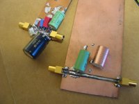
The actual test jig now looks like this:[I should have started with this]
But I concur totally with you, that measuring at around nH values is a task.
But, may I ask you what method would you suggest [possibly with my analyzer] to measure that effective capacitance change shown your figure earlier? I would suppose that I should measure the pole formed by a fixed resistance, for example my line impedance, and the deviations should show up like deviations from the 20db/decade declination straight line? The problem here is that the low freq capability of this S-parameter test set is limited at 10kHz..
Ciao, George
Oops, you are absolutely right. I was so pretentious that I supposed you know about my measurement method. I've introduced [it & myself]
here
At this post I've explained it a bit further, why is it measuring quite well - at least IMHO. why is it resistive?
As you see, I do not measure inductance - I measure bypass impedance from the attenuation, and I calculate the inductance values from this. This is not a calibrated precise value, but here, and in the majority of practical cases, we are talking about relative impedance changes. Though I would like to point out, that even in absolute terms this method can get quite close, as I have shown it in a thread at the another forum.
The actual test jig now looks like this:[I should have started with this]
But I concur totally with you, that measuring at around nH values is a task.
But, may I ask you what method would you suggest [possibly with my analyzer] to measure that effective capacitance change shown your figure earlier? I would suppose that I should measure the pole formed by a fixed resistance, for example my line impedance, and the deviations should show up like deviations from the 20db/decade declination straight line? The problem here is that the low freq capability of this S-parameter test set is limited at 10kHz..
Ciao, George
Attachments
- Status
- This old topic is closed. If you want to reopen this topic, contact a moderator using the "Report Post" button.
- Home
- Source & Line
- Digital Source
- Copper foil around electrolytic capacitors?