I'll post some pics in a little while. My VAS seems a little hot too. Do you run a sink on it? I measured r26 and it is 771mv. That's a little over 16mA. They are hot to the touch. Not blistering but hot. Not sure if that would cause any of this.
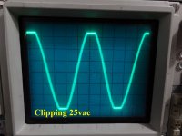
I couldn't see any oscillation, just a tone. I checked it against my tone generator and it is about 750hz.
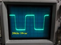
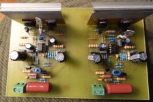
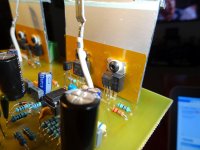
Here are some pics
I couldn't see any oscillation, just a tone. I checked it against my tone generator and it is about 750hz.
Here are some pics
Attachments
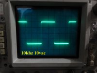
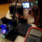
VAS current is about right and I use a heatsink - on the picture, the smaller heatsink on the left, lit by the blue LEDs, is the one attached to VAS. The other, bigger one, handles the drivers along with the Vbe spreader.
I still can't imagine the nature of the tone...
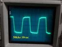
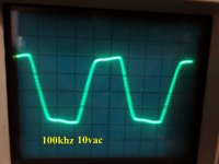
All the rest looks pretty fine. Some "teeth of a saw" at 50KHz and higher squares don't hurt - this is a slight high-frequency "ringing", that may decrease, or disappear, once you manage to make it working from +/-50V rails.
As a "crazy" idea - try to increase C14 - put some 0.1uF there. Will the tome still be there?
I still can't imagine the nature of the tone...
All the rest looks pretty fine. Some "teeth of a saw" at 50KHz and higher squares don't hurt - this is a slight high-frequency "ringing", that may decrease, or disappear, once you manage to make it working from +/-50V rails.
As a "crazy" idea - try to increase C14 - put some 0.1uF there. Will the tome still be there?
Attachments
VAS SMD Mosfets
What about PHC2300 from NXP?
http://www.nxp.com/documents/data_sheet/PHC2300.pdf
And now to think about to put it on double sided all SMD PCB. Try to find better VAS SMD mosfets which will be cooled down on PCB copper polygon, etc. for some more up-to date solutions.")
What about PHC2300 from NXP?
http://www.nxp.com/documents/data_sheet/PHC2300.pdf
I did a little more experimenting. Just touching the input cable changes the frequency of the tone. I tried just shorting the input with a 1" piece of wire. The tone is still there. If I attach a jumper wire to that shorting wire I can change the tone simply by wiggling that wire. I tried both input terminals with the same result. It is like it is picking up RF from somewhere. None of my other amps do this.
I did a little more experimenting. Just touching the input cable changes the frequency of the tone. I tried just shorting the input with a 1" piece of wire. The tone is still there. If I attach a jumper wire to that shorting wire I can change the tone simply by wiggling that wire. I tried both input terminals with the same result. It is like it is picking up RF from somewhere. None of my other amps do this.
I found this amp very particular to input wiring. I could set mine into oscillation with a shoddy quick connection. I wasn't too concerned because my protection board would always shut it down for me. I have no noise at all though and I'm running 50V rails.
I did a little more experimenting. Just touching the input cable changes the frequency of the tone. I tried just shorting the input with a 1" piece of wire. The tone is still there. If I attach a jumper wire to that shorting wire I can change the tone simply by wiggling that wire. I tried both input terminals with the same result. It is like it is picking up RF from somewhere. None of my other amps do this.
Can it come from the PC or something like that?
As another "experiment", you can add two 47pF caps underneath the board - between the base of Q7, Q8 (respectively) and the ground.
There is no PC. It is direct from a CD player. Same hookup I use for all my amps. The amp does this with nothing attached, shorted input or plugged into the CD player. I'll try the 47p and get back to you. I have to wonder why neither you nor Jeff have this. Quite the mystery.
OK here is what I did. I first installed 10p in C8. that didn't help. Then I installed 47p from the bases of Q7 & Q8 to ground. That seemed to work OK so then I tried removing C8 and the tone was back. I reinstalled C8. It is almost fixed. If I turn on with a speaker attached, the tone will wind up until the PSU finishes powering up and then the tone will fade but if I fool around with the input cable I can hear it slightly. At power off the tone will reappear and wind down. Not quite there IMO. I haven't tried reducing the VAS current yet. I planned to add a heatsink there.
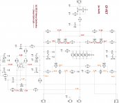
Terry, this is first of all for you now, as you already have it soldered.
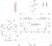
"As built" schematic is attached. Sorry - this one is from DipTrace, better presentation, but different numbering.
Leave R1, R2 as is (22R). It's good to set the VAS current with R8, R9.
R8, R9 = 1.6K -> VAS current = 8mA
R8, R9 = 1.5K -> VAS current = 5.3mA
Other adjustments:
C4 = 33pF
C3 = 220pF
That's it. Have fun! Let me know how it goes and what you hear
Cheers,
Valery
P.S. It's cool to have TO-220 hex-fets as VAS devices. I tried to abuse then even at 40mA - they work, getting just moderately warm
I also love the compensation here - one 33pF lead cap in parallel with GNFB resistor
Ah! One more thing. I've got 4 boards from PCB workshop, instead of 2 (for the price of 2

Hi Valery,
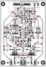
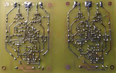
I made the changes but something is wrong. I'm attaching a board image with values. If you have time would you check it over and see if you find a problem? I haven't hooked it up to an OPS yet. I just put resistors between PD and ND and the NFB. I'm reading 65mA output so something is definitely wrong.
Thanks, Terry
Attachments
Last edited:
Hi Valery,
I made the changes but something is wrong. I'm attaching a board image with values. If you have time would you check it over and see if you find a problem? I haven't hooked it up to an OPS yet. I just put resistors between PD and ND and the NFB. I'm reading 65mA output so something is definitely wrong.
Thanks, Terry
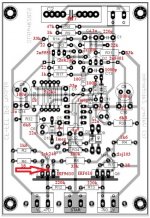
Hi Terry, I have checked everything I could and I don't see any mistakes (although, I have used the other layout, this one looks fine to me as well). I have replicated my boards twice and both times they worked fine right away.
Just one thing to check - is there no connection between 2SK246 gate and IRF9610 drain (they are pretty close to each other on the PCB - see the red "X".
Can you please measure the voltage drop over each of the following resistors:
- R2, R4;
- R6, R7;
- R5.
Then we'll see...
Thank you,
Valery
Attachments
Hi Terry,
This design utilizes a high-current (low impedance) NFB network - so the best way for standalone testing is to connect both outputs and NFB directly, without any resistors.
You can check the VAS current, measuring the voltage drop over R6, R7 (minus 2.5mA, running through R5). That's how I tested it.
1k5 instead of 1k6 will give slightly lower VAS current, however the circuit is expected to work anyway.
Cheers,
Valery
Hi Valery.
OK, I just used jumpers between PD and ND to the NFB. These are the readings I have.
+-45V rails
Right channel
R2 (1k5) = 5.94V
R4 (1k5) = 5.74V
R5 (33k) = 80V
R6 (18R) 1.19V
R7 (18R) 1.06V
Left channel
R2 (1k5) = 5.76V
R4 (1k5) = 6.43V
R5 (33k) = 78V
R6 (18R) 1.8V
R7 (18R) 1.8V
I'm attaching some pics in case that might help.
Thanks, Terry
Attachments
Last edited:
Hi Valery.
OK, I just used jumpers between PD and ND to the NFB. These are the readings I have.
+-45V rails
Right channel
R2 (1k5) = 5.94V
R4 (1k5) = 5.74V
R5 (33k) = 80V
R6 (18R) 1.19V
R7 (18R) 1.06V
Left channel
R2 (1k5) = 5.76V
R4 (1k5) = 6.43V
R5 (33k) = 78V
R6 (18R) 1.8V
R7 (18R) 1.8V
I'm attaching some pics in case that might help.
Thanks, Terry
Too much of VAS current... let me think a bit.
Too much of VAS current... let me think a bit.
Here is a schematic with voltages. Hopefully this will help.
Attachments
Terry, I have inspected my final build and also my CF-FET V2 with SMT parts gave me a clue.
First thing - I ave increased R1, R2 to 27R in the final build (and then forgot about it).
The other thing - as my SMT version has just shown - there may be some difference in transistors' parameters - even though we don't expect them to be that high.
So - please change R1, R2 to 27R and see what you measure over R6, R7 (the voltage will decrease). In case it's still high - increase R6, R7 to, say 47R or even more. The voltage will stay the same in this case, but the current will decrease because of the higher R values. You can do it with no hesitation, nothing will break, just the VAS current will decrease. My boards' VAS runs at 11mA (with addition of 2.5mA through R5, 13.5mA goes through R6, R7).
This part of the circuit is difficult to simulate because the simulated VAS current value is lower than the one I've got in the real life prototype.
First thing - I ave increased R1, R2 to 27R in the final build (and then forgot about it
).The other thing - as my SMT version has just shown - there may be some difference in transistors' parameters - even though we don't expect them to be that high.
So - please change R1, R2 to 27R and see what you measure over R6, R7 (the voltage will decrease). In case it's still high - increase R6, R7 to, say 47R or even more. The voltage will stay the same in this case, but the current will decrease because of the higher R values. You can do it with no hesitation, nothing will break, just the VAS current will decrease. My boards' VAS runs at 11mA (with addition of 2.5mA through R5, 13.5mA goes through R6, R7).
This part of the circuit is difficult to simulate because the simulated VAS current value is lower than the one I've got in the real life prototype.
Hi Valery,
I changed out R1 & R3 to 27R. Very little change.
I tried 47R for R6 & R7 and that brought it down a little.
I now have 68R there. For some reason the two channels are different. I'm guessing difference in gain of the various transistors but not sure. Here are the readings I'm getting now.
Left channel
R2 (1k5) = 5.619V = 374uA
R4 (1k5) = 5.507V = 366uA
R6 (68) = 1.311V = 19mA
R7 (68) = .922V = 13.59mA
Right channel
R2 (1k5) = 6.0V = 4mA
R4 (1k5) = 5.425V = 3.61mA
R6 (68) = 1.797V = 26.4mA
R7 (68) = 1.656V = 24.35mA
May I assume this IPS was developed with the Tubsumo OPS in mind? Is it possise this IPS with the Slewmaster? I think the IPS needs to be around 5mA.
Thanks, Terry
- Status
- This old topic is closed. If you want to reopen this topic, contact a moderator using the "Report Post" button.
- Home
- Amplifiers
- Solid State
- Cool simple "clean" CFA