This is a picture of what i have in mind...question is..would this concept pose any improvement compares to Vladimir's optimized HF-fet follower. Guess it comes down to what degrades sound the most, DC blocking caps....or an interstage transformer..??
Small interstage trafo is usually appreciated, even for volume control. I would love to hear somebody's report on what this concept could provide.
Single-ended amplifiers draw constant current.
Wuyit,Please, think about common source SE stage with simple resistive load, in pure class A, does it draw constant current from PS under signal?
you have fallen into the same trap that many have done before you.
SE amplifiers draw a constant quiescent bias, i.e. when no signal is present to be processed.
When a signal passes through the amplifier, the supply rail current is modulated in time and in value as the output current changes.
It is only when the speaker (load) is moved across to opposite the amplifier device "load" i.e. to the supply rail that the ClassA output current does not modulate the supply rail current in value.
As far as I know, this version of SE and the true balanced push pull ClassA are the only true constant current ClassA topologies.
None of the "normal" ClassA topologies draw constant current when delivering a variable load current.
I do not wish to get envolved in this arguement.
However I agree that every one is entitiled to there own views and opinions,reguardless.
I too have been shunned (ignored) as well for my views and for making simple mistakes without realizing it.
Many of my posts have been deleted because of my views ,when they should not have as there was a wealth of information to have been had.
I just get tired of starting too read a good thread only to find bickering and sarcasim instead.
I know of a few that are reluctant to post anything or don't anymore because of this including myself.
As I have mentioned I have been working on some class a designs of my own, lately.
But I won't be posting them to be ridiculed at.
Such as I have witnessed been displayed here.
That is my opinion and is all I have to say about it.
Good day gentlemen . jer
P.S. I hope that this can be turned back into something intresting again.
Seems to me, Pro's and Con's is a good title, as each may have its own application.
Since the driver current/voltage is the same for each, and in one case the power supply current is constant, that you have a choice as to the current path for the ac current.
If you add a bit of impedance to all connections and trace its effects with the ac current relative to the desired signal (including the inputs reference) you can make your choice. I was a bit surprised when I did this.
Thanks
-Antonio
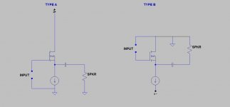
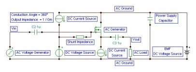
OOpsie, my bad, 2'nd circuit should be positive earth as shown below. Sorry, drew it wrong the first time.Godfrey,
I believe that once you couple a signal source to the right hand circuit, you will see that the PS ripple is back into the circuit, big time!
jan didden

As shown below, the 2'nd circuit should have good PSRR etc.
Attachments
When simulating the circuit.. theres no modulation on the power supply or ground what so ever....I did the same with GND as reference and then there is clear modulation...off course..the current sources in simulation are ideal..with unlimited impedance...but never the less they show quite big difference...so stating that the circuits are the same regardless of where the reference point is for the load..is simply stating something out of thin air...
Still wonder how the dual shunt would perform...
Still wonder how the dual shunt would perform...
Andrew,
¤
I was about to urge the combatants to differentiate between DC and AC in order to give some sort of meaning to the explanations that I generally find extremely muddy.
No trap. In post #29 I was explicitly referring to constant DC current. Dynamic AC load current is never constant.Wuyit,
you have fallen into the same trap that many have done before you.
SE amplifiers draw a constant quiescent bias, i.e. when no signal is present to be processed.
All Class A amps draw constant DC current in terms of no switching action occurs (Bias current = Imax). The methods for bias current setting and their qualities certainly deserve an examination (maybe in a different chapter).As far as I know, this version of SE and the true balanced push pull ClassA are the only true constant current ClassA topologies.
This does not make sense to me.When a signal passes through the amplifier, the supply rail current is modulated in time and in value as the output current changes.
It is only when the speaker (load) is moved across to opposite the amplifier device "load" i.e. to the supply rail that the ClassA output current does not modulate the supply rail current in value.
As far as I know, this version of SE and the true balanced push pull ClassA are the only true constant current ClassA topologies.
None of the "normal" ClassA topologies draw constant current when delivering a variable load current.
¤
I was about to urge the combatants to differentiate between DC and AC in order to give some sort of meaning to the explanations that I generally find extremely muddy.
Wuyit,
you seem to have the concepts of SE and constant current mixed up, judging by your response.
Post22 is clearly talking about the AC condition.
post29 quotes Forr and we can assume you mean AC as well.
Now you are saying you are only referring to the DC condition, which is usually the same as the no signal or quiescent condition.
If we take your garbled and mixed up response and compare a Class A to a ClassB to a ClassAB you will find that all these amplifiers draw a constant quiescent current from the supply rails when no signal is being processed.
Give us a break.
OK,
So it would seem to me the best way to go would be to use a p channel follower. That way the CCS is on top and the speaker can still be connected to ground but current draw will remain constant.
Seems like the obvious all round compromise provided there is no sonic disadvantage to using p channel fets - just started a thread about this.
Late now so will post a schematic tomorrow.
Thanks everyone for your comments. I have enjoyed watching this thread develop.
The amplifier I have built with help from everyone here (AndrewT especially) is playing now and sounding very sweet indeed....but it's on to the next design now
Yes, that's one way to do it. Alternatively, you can use an n-channel follower, and connect earth to the positive supply rail instead of the negative one. See post 46 for a simplified circuit.OK,
So it would seem to me the best way to go would be to use a p channel follower. That way the CCS is on top and the speaker can still be connected to ground but current draw will remain constant.
Either way you end up with:
a) Mosfet drain is connected to whichever PSU rail is grounded.
b) CCS is connected to the other PSU rail.
c) Input and output are both referenced to ground.
Alternatively, you can use an n-channel follower, and connect earth to the positive supply rail instead of the negative one. See post 46 for a simplified circuit.
Ah yes, thank you godfrey. I somehow missed that post. I like it, especially considering the flaws in p channel devices. A much neater solution.
I'm going to rearrange my amplifier circuit to suit. Will post a schematic later.
Regards,
Greg.
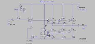
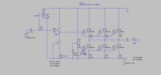
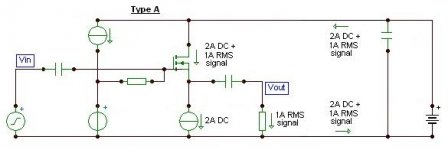
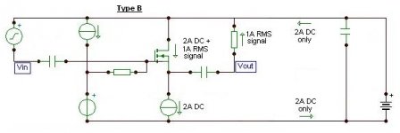
I simmed the two real life circuits shown below. Unexpectedly, with a simulated 1V supply ripple, the distortion improvement in the second design is almost negligible:
TYPE A (1V ripple) Total Harmonic Distortion: 0.108783%
TYPE B (1V ripple) Total Harmonic Distortion: 0.105883%
However, with a 3V ripple things get interesting:
TYPE A (3V ripple) Total Harmonic Distortion: 0.116670%
TYPE B (3V ripple) Total Harmonic Distortion: 0.105884%
You can see that the increase in supply ripple has a much lower affect on type b.
One would assume the difference would be more substantial in real life?
Now, a question for you experienced builders. How much ripple do we typically see in a heavily engineered non regulated PSU for a Class A amp? I think usually under a volt or two? So distortion improvement is probably minimal.
In any case, given the fact that each design is identical in terms of parts count, it would seem prudent to go with type b and be comfortable knowing you have chosen the lowest distortion design possible
Attachments
Last edited:
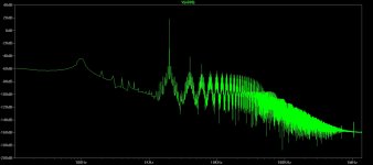
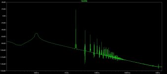
THD, .four is not what you want
PSRR is simply how much of the PS freq is at the output
a measure of "PS rail distortion" would be to look for intermodulation products between the PS ripple frequency and the signal at the output
to do that you need to look at the fft to see +-100 Hz sidebands on your excitation fequency at the output
you will need to run the sim for multiple ripple cycles - with Blackman window 5x is good to fully separate the peaks
(in LTspice its a good idea to add .option plotwinsize=0 to your schematic to turn off compression)
@swordfishy:
Hooray, nice demonstration of the difference!
btw FFTs are a bitch. To get accurate results, the interval needs to be a whole number of cycles of both the signal waveform and the ripple waveform (and any other input). It looks like you got that right though, with 100mS, 2kHz and 100Hz.
The other thing that screws up results is slow voltage drift during the measurement interval due to capacitors charging or discharging as the circuit's operating point settles. Two ways to fix that:
a) Let the sim settle before the measurement e.g. run the sim for 200mS but only do the FFT on the last 100mS.
b) Replace any large(ish) caps with appropriate voltage sources for the FFT test.
P.S. I left some comments your F4 thread as well - just found that now.
edit: oops, cross-posted with WuYit
Last edited:
Thanks Godfrey,
Looks like I lucked onto the right simulation interval I didn't know that - how do you people figure these things out!?
I think I'm suitably convinced of the difference to alter the design. As I said, the parts count is the same so it would be silly not to reap the benefits, which as far as I can tell are free in all respects.
Thanks for you comments in my other thread.
Going to go play with the circuit now.
Looks like I lucked onto the right simulation interval
I didn't know that - how do you people figure these things out!?I think I'm suitably convinced of the difference to alter the design. As I said, the parts count is the same so it would be silly not to reap the benefits, which as far as I can tell are free in all respects.
Thanks for you comments in my other thread.
Going to go play with the circuit now.
- Status
- This old topic is closed. If you want to reopen this topic, contact a moderator using the "Report Post" button.
- Home
- Amplifiers
- Solid State
- Constant Current Pros and Cons