I do recognize, that specific concept is present in Ciuffolli's paper, this concept is very important for sound quality - non passing of output alternating current through PS rails. Why is it important - it is another story.
Of course, one is free to say "wonderful" or "bull..." to everything, including relativity theory, IMHO.
Of course, one is free to say "wonderful" or "bull..." to everything, including relativity theory, IMHO.
The interesting idea in Ciuffoli's circuit is that a constant current is drawn from the power supply. Otherwise, sure, it's a simple common drain circuit.
I called it a shunt amplifier because it reminds active shunt DC regulators.
If it had some voltage gain and overall negative feedback, the loop stability had to be checked, just like any series circuit which most DC regulators and amplifiers indeed are.
A guy of a french forum built it and said he was statisfied.
Hi Jan,
")
They're the same, but Ciuffoli`s is worse.There's no conceptual difference between the two circuits.
Vladimir,
That`s a false concept.I do recognize, that specific concept is present in Ciuffolli's paper, this concept is very important for sound quality - non passing of output alternating current through PS rails.
Lumba,
It's not a false concept at all, it merely disagrees with your view of the world. I see some evidence of your cleverness, but none that you are infallible.
I am inclined to agree with Vladimir, having built another variant of this exact circuit, with a conventional power supply. I've not built Andrea's circuit, perhaps you haven't either, but from the schematic it is clear to me that it would offer superior resolution simply because it is quieter.
I disagree with many of the things you say, Lumba, but I don't see any good reason to proclaim it from the rooftops. It is actually childish - everyone is entitled to their POV, even it it's wrong, and that applies to all of us.
Ciao,
Hugh
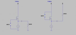
Assuming both circuits below are biased correctly, they will have the same max output. The one on the right has a couple of advantages though, which may not be obvious.
Firstly, Power supply rejection will be better. In the first circuit, any ripple voltage across the supply rails is also across the Mosfet, and a fraction of that will appear across the speaker. In the second circuit, the ripple voltage is across the CCS, rather than the Mosfet. Assuming a decent CCS is used, much less of that ripple will find it's way to the speaker.
Also, as has been pointed out, in the second circuit there is no signal current flowing in the power supply wiring, thus no signal voltage on the power supply rails. This is likely to give less crosstalk, especially in the case of a stereo amp using a single supply for both channels. There should also be less radiation of (audio) magnetic fields, if anyone cares.
Attachments
Also, as has been pointed out, in the second circuit there is no signal current flowing in the power supply wiring, thus no signal voltage on the power supply rails. This is likely to give less crosstalk, especially in the case of a stereo amp using a single supply for both channels. There should also be less radiation of (audio) magnetic fields, if anyone cares.
To me the most important is that this approach removes the PS electrolytics from the circled output signal chain, this gives better resolution, and during listening this effect 100% recognizable.
forr,
That interesting idea is much older than him. Single-ended amplifiers draw constant current. It seems to me that you (and some other people) tend to ascribe fictive features to this circuit.The interesting idea in Ciuffoli's circuit is that a constant current is drawn from the power supply.
forr,
That interesting idea is much older than him. Single-ended amplifiers draw constant current. It seems to me that you (and some other people) tend to ascribe fictive features to this circuit.
Please, think about common source SE stage with simple resistive load, in pure class A, does it draw constant current from PS under signal?
Hugh,
well, the misbeliefs related to power supply are numerous too. As I see it, despite the presence of the series pass element, Ciuffoli's approach is insufficient, resulting from his twisted view on the role of power supply electrolytic capacitors. It is nearly pointless to build an amp like this without a befitting (heavy and bulky) power supply.
By the way, I have difficulty finding the meaning of this:
well, the misbeliefs related to power supply are numerous too. As I see it, despite the presence of the series pass element, Ciuffoli's approach is insufficient, resulting from his twisted view on the role of power supply electrolytic capacitors. It is nearly pointless to build an amp like this without a befitting (heavy and bulky) power supply.
The question of importance is if it agrees with the state of the physical world and it verifiably does.It's not a false concept at all, it merely disagrees with your view of the world.
By the way, I have difficulty finding the meaning of this:
The currents through the mosfet and the speaker are conjugate; they always add to a constant, the current which passes through the CCS. And because the speaker is referenced to the positive rail (ground) and the CCS has very high impedance in the megohms to the negative rail, there is almost no hum at all despite modest filtering.
This approach marginally reduces dissipation in the source follower, too, giving symmetrical currents through it which inverse track speaker currents.
I do recognize, that specific concept is present in Ciuffolli's paper, this concept is very important for sound quality - non passing of output alternating current through PS rails. Why is it important - it is another story.
Of course, one is free to say "wonderful" or "bull..." to everything, including relativity theory, IMHO.
The output alternating current ALWAYS passes through the power supply - if not, there would be no power supplied
jan didden
godfrey,
On what basis is all this obvious to you?Firstly, Power supply rejection will be better. In the first circuit, any ripple voltage across the supply rails is also across the Mosfet, and a fraction of that will appear across the speaker. In the second circuit, the ripple voltage is across the CCS, rather than the Mosfet. Assuming a decent CCS is used, much less of that ripple will find it's way to the speaker.
Also, as has been pointed out, in the second circuit there is no signal current flowing in the power supply wiring, thus no signal voltage on the power supply rails. This is likely to give less crosstalk, especially in the case of a stereo amp using a single supply for both channels. There should also be less radiation of (audio) magnetic fields, if anyone cares.
Assuming both circuits below are biased correctly, they will have the same max output. The one on the right has a couple of advantages though, which may not be obvious.
Firstly, Power supply rejection will be better. In the first circuit, any ripple voltage across the supply rails is also across the Mosfet, and a fraction of that will appear across the speaker. In the second circuit, the ripple voltage is across the CCS, rather than the Mosfet. Assuming a decent CCS is used, much less of that ripple will find it's way to the speaker.
Also, as has been pointed out, in the second circuit there is no signal current flowing in the power supply wiring, thus no signal voltage on the power supply rails. This is likely to give less crosstalk, especially in the case of a stereo amp using a single supply for both channels. There should also be less radiation of (audio) magnetic fields, if anyone cares.
Godfrey,
I believe that once you couple a signal source to the right hand circuit, you will see that the PS ripple is back into the circuit, big time!
jan didden
Jan
I don't agree with with you...here in this case the current flowing is always the same..and of of course supplied by the PSU...but i works in a static manner....The active device then controls where this current flows if it's forced through the loudspeaker or shunted through the device... Because the active device and the speaker load shares the same reference point this loop becomes very small and local..
If the speaker load instead was referenced to GND.. you would put the PSU back in the loop and then you would would have to deal with the quality of the GND..as the load would try to modulate it...Thus changing the role of the PSU and the Capacitors and by that the quality and ammount requirement.
I have proposed a dual shunt string with the load placed in the middle and the active devices driven through a transformer with the center tap lifted (sinked) to the bias point by batteries from the rail..then the two strings can drive the load from the same voltage point and the DC blocking cap could be removed..Push pull not really...or..??
Last edited:
Lumba, you apparently don't understand my commentary here:
I know why; you and I have left and right handed brains and we use very different words to describe the same phenomenon. I'll give it another go.
The current source supplies both the active mosfet AND the speaker.
Therefore, if the speaker current increases, then the active device current decreases, and by the precise same amount. This also happens with an LTP, and is called a conjugate current. It relies on Kirchoff's law, whereby one current coming from a node must sum to any and all currents coming into the node; a re-expression of the law of conservation of energy, nothing simpler.
Both the active device and the speaker lie in paralel between the positive rail (which is ground) and the CCS. The reference, (since the CCS presents a very high impedance to both devices precisely because voltage changes across it result in negligible current change through it) can only the positive rail, which I stress again is ground.
If the reference for both active device and speaker are the same, and BTW shared with the input signal whose reference is also ground, then the sources of differential voltage which normally are amplified to produce hum are completely absent in this design.
To the extent that the current source is imperfect, and presents some impedance to the negative rail, there will always be some residual hum. But it is small, represented approximately by the ratio of the ground impedance of the active device to the dynamic impedance of the CCS multiplied by the ripple voltage measured wrt ground at the negative rail of the supply. I would think this would be in the microvolts.
Jan correctly points out that one circuit has much higher current delivery on one half of the waveform, but highlights that within clipping limits the rms output is identical. Absolutely correct, BUT, this also means that the Ciuffoli circuit has slightly lower dissipation, which of course manifests as slightly higher efficiency, because on positive and negative peaks the currents through the active device move up and down in antiphase to the speaker currents - precisely because the active device and speaker currents are conjugate.
The circuit is tricky to analyse because it represents a form of optical illusion; is it a grecian urn, or a face?
Hugh
The currents through the mosfet and the speaker are conjugate; they always add to a constant, the current which passes through the CCS. And because the speaker is referenced to the positive rail (ground) and the CCS has very high impedance in the megohms to the negative rail, there is almost no hum at all despite modest filtering.
This approach marginally reduces dissipation in the source follower, too, giving symmetrical currents through it which inverse track speaker currents.
I know why; you and I have left and right handed brains and we use very different words to describe the same phenomenon. I'll give it another go.
The current source supplies both the active mosfet AND the speaker.
Therefore, if the speaker current increases, then the active device current decreases, and by the precise same amount. This also happens with an LTP, and is called a conjugate current. It relies on Kirchoff's law, whereby one current coming from a node must sum to any and all currents coming into the node; a re-expression of the law of conservation of energy, nothing simpler.
Both the active device and the speaker lie in paralel between the positive rail (which is ground) and the CCS. The reference, (since the CCS presents a very high impedance to both devices precisely because voltage changes across it result in negligible current change through it) can only the positive rail, which I stress again is ground.
If the reference for both active device and speaker are the same, and BTW shared with the input signal whose reference is also ground, then the sources of differential voltage which normally are amplified to produce hum are completely absent in this design.
To the extent that the current source is imperfect, and presents some impedance to the negative rail, there will always be some residual hum. But it is small, represented approximately by the ratio of the ground impedance of the active device to the dynamic impedance of the CCS multiplied by the ripple voltage measured wrt ground at the negative rail of the supply. I would think this would be in the microvolts.
Jan correctly points out that one circuit has much higher current delivery on one half of the waveform, but highlights that within clipping limits the rms output is identical. Absolutely correct, BUT, this also means that the Ciuffoli circuit has slightly lower dissipation, which of course manifests as slightly higher efficiency, because on positive and negative peaks the currents through the active device move up and down in antiphase to the speaker currents - precisely because the active device and speaker currents are conjugate.
The circuit is tricky to analyse because it represents a form of optical illusion; is it a grecian urn, or a face?
Hugh
Last edited:
- Status
- This old topic is closed. If you want to reopen this topic, contact a moderator using the "Report Post" button.
- Home
- Amplifiers
- Solid State
- Constant Current Pros and Cons