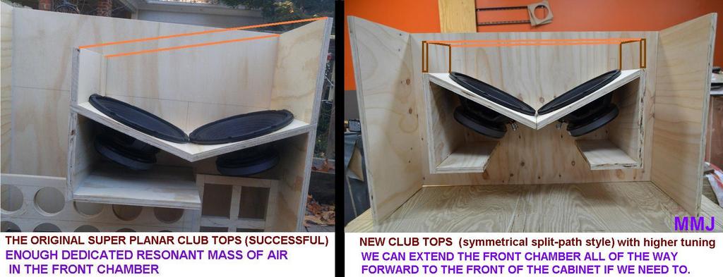
About that front chamber
About the front chamber on the Super Planar tops ........ For a tuning of around 60hz or 65hz we know that the amount of dedicated resonant air mass that we had in the front chamber of our original club tops was enough to fill in the response hole just above the Fbx3 harmonic and therefore produced excellent midbass ...
...
Our line-array module style tops did not have enough dedicated resonant air mass in the front chamber because there was still somewhat of a dip just above the Fbx3 harmonic in this case which suggests they were operating more like QWPs or "TL" cabinets due to the marginal front chamber depth .....
With higher tunings on the main path it means that the requirements for the dedicated front chamber volume are reduced by a little .......
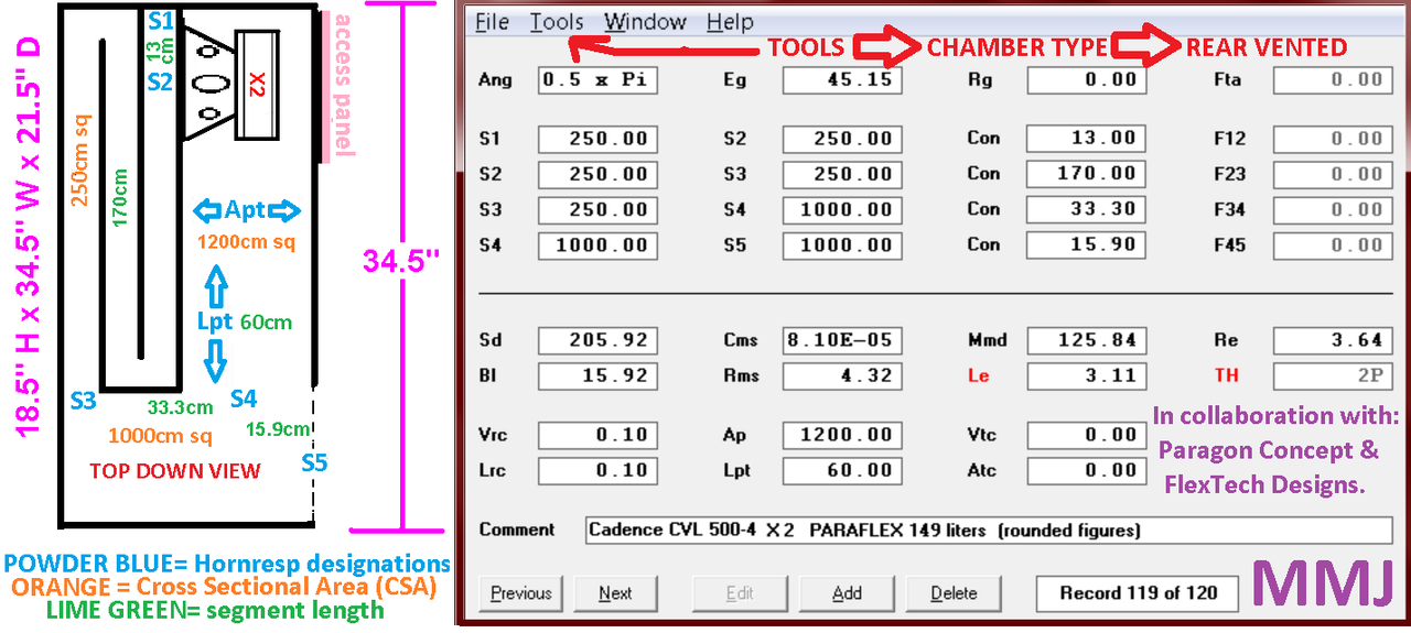
Mr Vansickle's current nightclub build involves Super Planar tops that are tuned higher and should end up with a fundamental of around 70hz to 75hz Fb... Unfortunately since Hornresp isn't perfect at predicting the required depth of the front chamber (it calculates the front chamber as either a square or round tube but certainly not a wide rectangle) we are left with trying to get a feel for what is needed ...
Getting some measurements of his new tops with various sized removable front chamber extension panels should help us get a better feel for the required depth .... We will be working on that this coming week .. ...
About the front chamber on the Super Planar tops ........ For a tuning of around 60hz or 65hz we know that the amount of dedicated resonant air mass that we had in the front chamber of our original club tops was enough to fill in the response hole just above the Fbx3 harmonic and therefore produced excellent midbass
... Our line-array module style tops did not have enough dedicated resonant air mass in the front chamber because there was still somewhat of a dip just above the Fbx3 harmonic in this case which suggests they were operating more like QWPs or "TL" cabinets due to the marginal front chamber depth .....
With higher tunings on the main path it means that the requirements for the dedicated front chamber volume are reduced by a little .......
Mr Vansickle's current nightclub build involves Super Planar tops that are tuned higher and should end up with a fundamental of around 70hz to 75hz Fb... Unfortunately since Hornresp isn't perfect at predicting the required depth of the front chamber (it calculates the front chamber as either a square or round tube but certainly not a wide rectangle) we are left with trying to get a feel for what is needed ...
Getting some measurements of his new tops with various sized removable front chamber extension panels should help us get a better feel for the required depth .... We will be working on that this coming week .. ...
Last edited:
Final revision on this one ....... May it be ..
Somehow with all of the adjustments i made on this i forgot to update some part and miscalculated the outer depth dimension in the sketch at post# 605 ....
Matt Schlobohm is getting ready to build this cabinet and as we were going over the details I spotted the problem .... . It is now fixed in this revision ...
I double checked and everything is looking good to me now but it is possible that i can miss some small detail, it happens sometimes, after all there is a lot going on here ....... Anyone can feel free to check my math ...
More updates to come ..... Dustin Morgan has some great response measurements of his Paraflex 12 that i need to share ....
Another fellow just built a Paraflex 15 for a Massive brand Gordo 15" driver ..... He is loving it !! ... He can't stop talking about it! Hehehe ... . I need to make a post about it but he has yet to get response measurements (working on it) and didn't provide very many build photos .. .... He did however post many videos on facebook , the microphone was terribly overloaded in his videos but at least you could see how the Paraflex was generating immense pressure inside of his car ... The amount of violence being produced by a single 15" driver in a Paraflex is impressive .. .... Efficiency is very high and bandwidth is excellent (for a high order cabinet with such a driver) , a combination not often seen in Car Audio ..
So far the Paraflex is turning out to be a big hit in Car Audio , now it is time to prove this design for PA applications and home audio
Somehow with all of the adjustments i made on this i forgot to update some part and miscalculated the outer depth dimension in the sketch at post# 605 ....
Matt Schlobohm is getting ready to build this cabinet and as we were going over the details I spotted the problem .... . It is now fixed in this revision ...
I double checked and everything is looking good to me now but it is possible that i can miss some small detail, it happens sometimes, after all there is a lot going on here ....... Anyone can feel free to check my math ...
More updates to come ..... Dustin Morgan has some great response measurements of his Paraflex 12 that i need to share ....
Another fellow just built a Paraflex 15 for a Massive brand Gordo 15" driver ..... He is loving it !! ... He can't stop talking about it! Hehehe
... . I need to make a post about it but he has yet to get response measurements (working on it) and didn't provide very many build photos .. .... He did however post many videos on facebook , the microphone was terribly overloaded in his videos but at least you could see how the Paraflex was generating immense pressure inside of his car ... The amount of violence being produced by a single 15" driver in a Paraflex is impressive .. .... Efficiency is very high and bandwidth is excellent (for a high order cabinet with such a driver) , a combination not often seen in Car Audio .. So far the Paraflex is turning out to be a big hit in Car Audio , now it is time to prove this design for PA applications and home audio
Dimensions for Gerald's Paraflex 15
Gkh ,
We have just what you need Gerald.
Referring back to the sketches and screenshots from post #644 your outer dimensions will be 95.5cm High x 43cm Wide x 90cm Deep .
It is using the layout seen at post #644 but with the cabinet width reduced to 43cm. You can see the 15LB100 driver listed under the 43cm width section to the lower left of the layout sketch image .... There is also the CSA conversion instructions in orange ...
Below (lower image from post #644) you will see the screenshot of Hornresp inputs specifically for your 15LB100 Paraflex cabinet, this one has the CSAs all calculated out for you already..
Let me know if you have any questions. .
Matthew,
are the dimensions dor the 15LB100 ParaFlex final? I'd love to have the panels cut
Gkh ,
We have just what you need Gerald
. Referring back to the sketches and screenshots from post #644 your outer dimensions will be 95.5cm High x 43cm Wide x 90cm Deep .
It is using the layout seen at post #644 but with the cabinet width reduced to 43cm. You can see the 15LB100 driver listed under the 43cm width section to the lower left of the layout sketch image .... There is also the CSA conversion instructions in orange ...
Below (lower image from post #644) you will see the screenshot of Hornresp inputs specifically for your 15LB100 Paraflex cabinet, this one has the CSAs all calculated out for you already..
Let me know if you have any questions
. .
Last edited:
An externally hosted image should be here but it was not working when we last tested it.
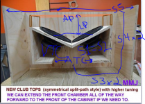
When modeling these, could you please explain why you choose to not treat the volumes in front and behind the drivers as volumes? I'm having a hard time wrapping my head around the Vrc and Lrc being 0.1, instead of modeling this as you would a Cubo design, with the volume behind the drivers (Vrc) and making S1=S2. Then using the Vtc and Atc to capture the volume in front of the drivers, instead of using the Ap and Lpt I kept in the pic.?
P.S. sorry for the cheesy scriblings, I hope you can make out what I'm trying to ask from the picture.
Attachments
When modeling these, could you please explain why you choose to not treat the volumes in front and behind the drivers as volumes? I'm having a hard time wrapping my head around the Vrc and Lrc being 0.1, instead of modeling this as you would a Cubo design, with the volume behind the drivers (Vrc) and making S1=S2. Then using the Vtc and Atc to capture the volume in front of the drivers, instead of using the Ap and Lpt I kept in the pic.?
P.S. sorry for the cheesy scriblings, I hope you can make out what I'm trying to ask from the picture.
Fidstang,
You can model a compression chamber behind the drivers if you like by using Vtc and Atc , i have modeled it this way before and it does work just fine .. In this case you would reduce the S12 length down to .1cm ... You can then reduce the CSA of S1 & S2 to a very low value which becomes the throat of the horn and flares out with expansion in the rest of the horn segments to complete our main path of the horn ...... This method works but i did not observe any advantages in the simulation over the way i typically model these cabinets .... I can show you what it would look like in a sketch if you like , we may try building them this way some time (with a compression chamber followed by S1 with small CSA as the horn's throat) to see if it sounds any different in the real world ..
Since this design uses compound loading (unlike the Cubo) we have our dedicated resonant mass of air in front of the drivers which we could call the front chamber & resonator but in Hornresp it is referred to as "Rear Vented" , nevertheless this is composed of Vrc & Lrc along with Ap and Lpt ............................................... I chose to mainly use Ap and Lpt to form that chamber/resonator going with minimal values for Vrc and Lrc but you can reverse that scheme by reducing Lpt to a very low value and then forming that section out of Vrc and Lrc but once again the results are basically the same ..
In Hornresp's "TH" mode we can model designs like the The Cubo , Tapped Horns, TPQWR (ROAR) , Classic Transflex (sometimes called "Tapped Pipe") , and also the PARAFLEX (SP8th variant) ..... With the Paraflex being the only compound loaded design out of that bunch..
The non-path-merged (or minimally-path-merged) Super Planar and Super Planar 8th cabinets use "OD" mode in Hornresp , which is the same mode used for QWPs ("TL") and OD-QWP ("TL") , ML-QWP (ML-TL) , Scoops , Back Loaded Horns (Rear loaded Horns) , Voigt Pipes, TQWPs , ML-TQWPs etc but once again the only compound loaded designs in this group are the Super Planars ...
The Paraflex and the Super Planar 8th are very similar with the exception of the paths merging significantly near the mouth with our Paraflex .......
However, as you may have noticed with some of our Super Planar tops we have the divider panel trimmed back by just a few inches to allow a small amount of merging at the very end of the paths , but it is minor ....... The length and shape of that divider panel (near the ends of the paths) is worth trimming and experimenting with because it should alter and contour the midrange response somewhat ... It may prove useful in fine-tuning the response of the cabinet........................... As Mr Vansickle is building the current set of Super Planar tops for the nightclub he is going to try to find the time to get some measurements while making alterations to the divider panel ................ On these particular boxes we may have to go without any path merging by bringing those dividers all the way to the front of the cabinet in order to get enough dedicated air volume in that front chamber to fill in the pesky midbass dip or hole just above the FbX3 harmonic ....
Last edited:
Happy Solstice, Saturnalia , Christmas , Hannukah, Kwanzaa, Krampusnacht, FESTIVUS!!
Gerald, I can relate,
Things can be delayed here in the states as well during the holidays ...
Why must the holidays be so inconvenient??!?!? Hehehe


Sometimes I really hate Xmas holidays: the wood will arrive after Jan 7th, 2018
Gerald, I can relate,
Things can be delayed here in the states as well during the holidays ...
Why must the holidays be so inconvenient??!?!? Hehehe
Last edited:
Fidstang,
You can model a compression chamber behind the drivers if you like by using Vtc and Atc , i have modeled it this way before and it does work just fine .. In this case you would reduce the S12 length down to .1cm ... You can then reduce the CSA of S1 & S2 to a very low value which becomes the throat of the horn and flares out with expansion in the rest of the horn segments to complete our main path of the horn ...... This method works but i did not observe any advantages in the simulation over the way i typically model these cabinets .... I can show you what it would look like in a sketch if you like , we may try building them this way some time (with a compression chamber followed by S1 with small CSA as the horn's throat) to see if it sounds any different in the real world ..
Since this design uses compound loading (unlike the Cubo) we have our dedicated resonant mass of air in front of the drivers which we could call the front chamber & resonator but in Hornresp it is referred to as "Rear Vented" , nevertheless this is composed of Vrc & Lrc along with Ap and Lpt ............................................... I chose to mainly use Ap and Lpt to form that chamber/resonator going with minimal values for Vrc and Lrc but you can reverse that scheme by reducing Lpt to a very low value and then forming that section out of Vrc and Lrc but once again the results are basically the same ..
In Hornresp's "TH" mode we can model designs like the The Cubo , Tapped Horns, TPQWR (ROAR) , Classic Transflex (sometimes called "Tapped Pipe") , and also the PARAFLEX (SP8th variant) ..... With the Paraflex being the only compound loaded design out of that bunch..
The non-path-merged (or minimally-path-merged) Super Planar and Super Planar 8th cabinets use "OD" mode in Hornresp , which is the same mode used for QWPs ("TL") and OD-QWP ("TL") , ML-QWP (ML-TL) , Scoops , Back Loaded Horns (Rear loaded Horns) , Voigt Pipes, TQWPs , ML-TQWPs etc but once again the only compound loaded designs in this group are the Super Planars ...
The Paraflex and the Super Planar 8th are very similar with the exception of the paths merging significantly near the mouth with our Paraflex .......
However, as you may have noticed with some of our Super Planar tops we have the divider panel trimmed back by just a few inches to allow a small amount of merging at the very end of the paths , but it is minor ....... The length and shape of that divider panel (near the ends of the paths) is worth trimming and experimenting with because it should alter and contour the midrange response somewhat ... It may prove useful in fine-tuning the response of the cabinet........................... As Mr Vansickle is building the current set of Super Planar tops for the nightclub he is going to try to find the time to get some measurements while making alterations to the divider panel ................ On these particular boxes we may have to go without any path merging by bringing those dividers all the way to the front of the cabinet in order to get enough dedicated air volume in that front chamber to fill in the pesky midbass dip or hole just above the FbX3 harmonic ....
Thank you very much, MMJ, for taking the time to write that out. I would love to see some diagrams, if you have time, so I can make sure that I'm really understanding what you are trying to convey. Also, excited to see how this symmetrical design works out, as I would like to desig something similar, but with the PA255-8's instead.
Hehe
Did you ever try building an edible sub?
Thank you very much, MMJ, for taking the time to write that out. I would love to see some diagrams, if you have time, so I can make sure that I'm really understanding what you are trying to convey. Also, excited to see how this symmetrical design works out, as I would like to desig something similar, but with the PA255-8's instead.
No problem Fidstang , i will put together a sketch or diagram for posting here soon .. ....
The PA255-8 should work although it's not an ideal 10 for this job, mostly due to a lack of motor force ... On the other hand It's bigger brother the PA310 has proven itself to be adequate in these Super Planar tops ....
A set of PA310s with HIGH-Q LPF for a 2khz crossover point to some low cost Dayton DT250P (or D250P) compression drivers would be a fun, simple and effective shoestring budget build...

MMJ - can U fudge H-PAS w. hornresp?
Freddi ,
I am not sure how we could make that happen, or at least i am not sure how an H-PASS cabinet would be modeled in Hornresp ...
 ..
..If the front of the drivers (that would normally be direct radiating in the H-PAS cabinet) were instead turned inward to play into the H-PASS chamber which happens to be vented into a tap near the mouth then we could definitely make that happen , with a long main path it would basically be a PARAFLEX ... Hehehehe
........... The sort of thing which is best suited for just low frequencies . Akabak will model an H-PASS for sure ... I have made a few H-PASS scripts long ago when trying out different configurations for the Karlflex ... As far as i could tell the H-PASS didn't seem to offer any benefit over the resonator and stub methods that we had devised at the time .... .So i passed on the H-PASS
Hehe
Did you ever try building an edible sub?
I think MDF is not that much different from gingerbread crackers in terms of strength and resistance to moisture
..... It is probably all made in the same factory anyhow .. . by Elves of course ..I think MDF is not that much different from gingerbread crackers in terms of strength and resistance to moisture
ROFL
I gather that H-PAS can work - with a price for small drivers. 30 some years ago I briefly had Phase Research 2- way boxes with an 8" and large Audax dome.
if one wishes to make a single driver PA310-8 Super Planar - would the symmetrical path be the first choice? - or the other way?
if one wishes to make a single driver PA310-8 Super Planar - would the symmetrical path be the first choice? - or the other way?
Who needs symmetry?
Freddi,
So far there are no observed benefits from going symmetrical with the cabinet layout, although people just seem to appreciate the look of it ..
With dual drivers the offset/spanned-driver (asymmetrical) version may actually play more smoothly through the midrange , and i suspect this has something to do with the multiple driver offsets and the additional dedicated resonant mass of air in the front chamber...
With a single driver I don't think there is going to be much difference between the two layouts except for the fact that the symmetrical box is more costly in terms of material and weight and complexity ....... So I say you might as well keep it simple unless you really just love the look of the symmetrical cabinet ......
With a single driver it means there is no crossfiring toed-in style baffle so you can expect it to be directional if you are running it to the upper midrange which you certainly could do with the PA310 using the HIGH-Q LPF up in the 1.5khz to 2khz region ........Best listening would definitely be exactly on-axis in this case .... .......... NOTE: Perhaps dispersion could be improved by modifying the shape of the front chamber to make it more like a short horn with phase plug, or possibly adding diffusion, or even panels to make it like a sectoral horn .. .
if one wishes to make a single driver PA310-8 Super Planar - would the symmetrical path be the first choice? - or the other way?
Freddi,
So far there are no observed benefits from going symmetrical with the cabinet layout, although people just seem to appreciate the look of it ..
With dual drivers the offset/spanned-driver (asymmetrical) version may actually play more smoothly through the midrange , and i suspect this has something to do with the multiple driver offsets and the additional dedicated resonant mass of air in the front chamber...
With a single driver I don't think there is going to be much difference between the two layouts except for the fact that the symmetrical box is more costly in terms of material and weight and complexity ....... So I say you might as well keep it simple unless you really just love the look of the symmetrical cabinet ......
With a single driver it means there is no crossfiring toed-in style baffle so you can expect it to be directional if you are running it to the upper midrange which you certainly could do with the PA310 using the HIGH-Q LPF up in the 1.5khz to 2khz region ........Best listening would definitely be exactly on-axis in this case .... .......... NOTE: Perhaps dispersion could be improved by modifying the shape of the front chamber to make it more like a short horn with phase plug, or possibly adding diffusion, or even panels to make it like a sectoral horn .. .
- Home
- Loudspeakers
- Subwoofers
- Compound loading 6th order quarterwave "Super Planar" horns and pipes concepts/builds