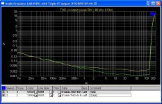
Can you explain why the 10W setup has more distortion at HF?
For 10 W output power, background noise dominates the THD+N for larger measurement bandwidths (noise limited). Here are 1 kHz and 10 kHz THD+N vs output power for various measurement bandwidths.
Here is THD+N vs output power for BW=80kHz for 1 kHz and 10 kHz tones. We can see that noise power is larger than THD power until output power is about 50 W.
Attachments

Hi Everyone,
Just a brief-small piece of input with regards to several years of listening tests and measurements on the parts you are all talking about here (that I had a very small hand in developing).
The best sounding amp we built was with the 49811. (actually two amplifiers, one with 50 VDC rails and one with 75VDC rails which was actually built for the 810 and we modified the board to accept the 811. The 811 version of the 75VDC unit measured the same as the 75VDC LME49810 unit but to my ear, and several others, sounded better. The 810 had an extra class AB stage added to its output to get the 50ma of extra output drive current. The 811 only is about 7ma but is pure class A!) The 811 part also had some internal changes by Mr. Bob Pease (and myself) that improved low-level performance...just my 2 cents worth (where did that phrase come from?)
The LME49830 was created just for FET's and was my third favorite sounding part of the 3, although still better than just about anything else out there! All three are very, very close to each other! In a finished amplifier the 830 did not measure quite as well as the 810/811. But then again I am not, and have never been, a FET guy!
Check out all three data sheets and the LM4702 data sheet as well.
Mark / audioman54
Hi Mark
A few questions comparing 49810 and 49811/4702.
Let say we want to use the 49xxx with a Leach output topology ( so no Sanken Darlington ). The advantage of this topology is well known ( loading on Vas including lower non linear input capacitance, output impedance, class A drivers ..).
If we use the output transistors of the LME49810 as class A pre pre driver or if we use the LME49811 with the same external class A push pull pre pre driver, what could be the difference?
Did you made your listening of the two chips with the same loading power Stage ( the Sanken Darlingtons) ?
Looking at the open loop spec on the data sheet, the LME49810 is different than the 811. The 810 open loop graph doesn't seem right to me. It looks like the open loop plot of an allready Miller compensated amp ( single pole). Pure open loop should show higher first pole and some other poles. It is usefull to know that if we want to experiment with twin pole compensation ( see very good book from Roberge on this ).
Can you be more specific on Peace/yours low level improvments of the 811.
How could you describe the listening difference between the two chips?
Thanks
Jean-Pierre
a very good question.Let say we want to use the 49xxx with a Leach output topology ( so no Sanken Darlington ). ...............
If we use the output transistors of the LME49810 as class A pre pre driver or if we use the LME49811 with the same external class A push pull pre pre driver, what could be the difference?
Did you made your listening of the two chips with the same loading power Stage ( the Sanken Darlingtons) ?
Is the 811 with a 3stage EF as output the near equivalent to the 810 with a 2stage EF?
Why should these two sound different?
Can the 10 and 11 devices be used with mosfets as well? I see no reason that when using a predriver that the 10 and 11 can not function in this capacity. Any input? I like the class A part of the frontend in the 11 device and would prefer to use it with the 240/9240 output section instead of the lme49830.
In the app note 1850 the national engineers were not able to discern any sound changes when using the darlington configuration over predriver. Maybe modern darlington devices have improved along the same lines as the FETS from earlier years.
Panson, I guess in your tests you were not able to actually HEAR any differences with these devices. And yes please publish the pcb's when you have them updated. I am in the process of installing your frontend boards in my 12 mosfets per rail A-75. I just need to figure out if a pre-pre driver such as Leach used would be if any benefit to drive the output. Nice work you are doing here.
Tad
Tad
a very good question.
Is the 811 with a 3stage EF as output the near equivalent to the 810 with a 2stage EF?
Why should these two sound different?
I have tried these two configurations: 49810 + two-stage EF and 49811 + three-stage EF. From measurement results, I would say they are equivalent. I can't hear any difference as well. Sorry, I don't have "golden ears" and high-definition speakers.
You are not alone. More than you know have not golden ears but they claim they have.....I can't hear any difference as well. Sorry, I don't have "golden ears" ....

Jack in Jersey,
And for some reason the LME49830 is two and half times more. Go figure!
Panson,
Have you noticed any heat issues during your experiments. A nice sized heatsink is a must for these chips.
I have not seen any information in the National docs related to input hardware. Do you need a good buffer or will a passive pre suffix?
Need some help here
Guys,
I need some with bais on a LME49811 driving a Leach type triple with Thermal Traks as the output transistor(s). I'm using the schematic by Bob Cordell from the Thermal Trak thread(attached) for the current amp section and the National schematic for the front end. The source lead goes to the "vspreadp" and the sink to the "vspreadn". With the input shorted, and a +-33vDC from my power supply, I get approx. 0.49v at the point Bob labeled vb6, but no volts at R7 - the point Bob labeled "vt". Is my voltage to low to get the required current and voltage to turn on the NJL3281/NJL1302's? The amp play, and even sounds nice, I get a clean sine wave, without cross over bumps.
Any thoughts would be appreciated.
Attachments
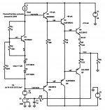
if you set up ~1.2V across the output bases you will get ~20mV across each Re and 1200mV across R6 giving the 60mA driver bias current.
That in turn requires ~2.4V across the driver bases and biases the pre-drivers to 10mA.
This requires the Vbe multiplier to generate ~3.6V
That in turn requires ~2.4V across the driver bases and biases the pre-drivers to 10mA.
This requires the Vbe multiplier to generate ~3.6V
Your outputs are turned on if you have no crossover distortion. Did you measure the voltage across R7 or from ground to "Vt"? If the latter, may be you include some offset into your measurement.
I tried it both ways. I measured the voltage from the base of the output transistors to ground and the voltage across the Re's and from NPN base to PNP base all were at 0v DC and base to base was .007vAC.
if you set up ~1.2V across the output bases you will get ~20mV across each Re and 1200mV across R6 giving the 60mA driver bias current.
That in turn requires ~2.4V across the driver bases and biases the pre-drivers to 10mA.
This requires the Vbe multiplier to generate ~3.6V
Where do I measure the Vbe voltage from the base of the Vbe transitor to ground?
Panson,
Have you noticed any heat issues during your experiments. A nice sized heatsink is a must for these chips.
I have not seen any information in the National docs related to input hardware. Do you need a good buffer or will a passive pre suffix?
Yes, THD gets higher if heatsinking is not sufficient.
I use passive (vol pot) for testing so far. For a finished amp, I will add an op-amp buffer.
Where do I measure the Vbe voltage from the base of the Vbe transitor to ground?
Sorry I meant from the emitter of the Vbe transistor to ground.
Sorry I meant from the emitter of the Vbe transistor to ground.
Did you measure base-to-base of Q2 and Q3 voltage?
Did you measure base-to-base of Q2 and Q3 voltage?
No, I measured from emitter to emitter, is that what I'm doing wrong?
Did you measure base-to-base of Q2 and Q3 voltage?
So, I just measured base-to-base between Q2 and Q3 = 0.509v dc.
I also measured the emitter voltage of Vbe transistor to ground 1.91v dc.
thoughts?
thanks again for the help.
Ken
- Status
- This old topic is closed. If you want to reopen this topic, contact a moderator using the "Report Post" button.
- Home
- Amplifiers
- Chip Amps
- Comparing LME49810, 49830 and 49811