Can anyone beat this?
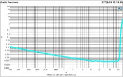
Hard to beat! Is LM49811 in inverting configuration as indicated by the caption of the graph?
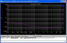
Here is what I can get right now for LME49811 with output triple.
Attachments
Hi Panson,
Yours is very very good! Especially considering you have a triple output.
Yes the unit I built is inverting. That was the only graph I had but there were some better ones on my lab computer at National.
Good Job!
Mark / Audioman54
Thank you Mark. Is inverting a better configuration for this chipamp as LM3886?
In my listening tests before I was laid off I felt inverting was better as did some others. Measured about the same though on all our standard tests (which did include FFT's-some else asked me if we looked at FFT's).
Have you posted your schematic (I have not looked back through all the threads).
I was running 50VDC rails on the graph what are you running on yours?
Mark
Have you posted your schematic (I have not looked back through all the threads).
I was running 50VDC rails on the graph what are you running on yours?
Mark
Audioman54,
What are the main differences internally of the 3 chips. Considering the cost of implementing this framework into such a small area I would think the chips would have major design differences.
I have a set of boards I got from Panson and plan on using them to drive the outputs on my A-75 amp any ideas on the layout for the driver device. There are 12 pairs on each channel at 70 volt rails. Should I use a predriver or will just one main driver suffice?
Panson,
Have you noticed any sonic listening differences in your comparisons? The numbers are good, but can you hear any changes. The only other chip amp I have is the LM3886 and it can be quite bright in the mid's at times.
Tad
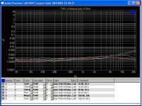
Are the THD graphs done at 1kHz?
jd
Yes, this is 1 kHz.
Panson,
Have you noticed any sonic listening differences in your comparisons? The numbers are good, but can you hear any changes. The only other chip amp I have is the LM3886 and it can be quite bright in the mid's at times.
Tad
Sorry, I can't hear any differences so far. It may need golden ears to tell the difference, or very good system and environment.
Last edited:
")
Any curves for 10kHz or 20kHz
jd
Yes, here you go THD vs freq vs power.
Attachments
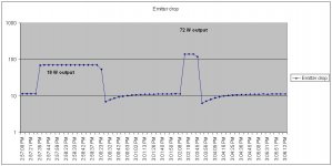
Here is measured data for 49810 with ThermalTrak. The idle current is set to 50 mA. One emitter resistor voltage drop was monitored. Output power varied from zero to 18 W, back to zero, and from zero to 72 W. The tracking is much faster compared to the previous data for Vbe multiplier for triple-EF output.
Attachments
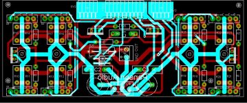
I am working on a new power board layout for four-pair ThermalTrak. Hopefully, it will be finished this week. I will do the same for 3-lead output devices. Here is a draft. Please comment.
Panson,
I'm not an expert on this, but, I have a couple of thoughts.
If you used 90deg board to board connectors instead of the straight connectors, you could put the LME49811 board at the end of this board instead of at the top center. Let's say you put it at the left edge - just for the sake of clarity in my example. Then you could put the VCE, gnd and VEE at the right edge of the board. The PNP's could be along the top edge and the NPN's could be along the bottom edge of the board. the output trace could run down the middle. This would prevent the power from crossing the output and the low current drive signal traces.
The second thought is that your power and signal output traces look a little narrow. With all these devices, it would seem you are preparing to run pretty high current. I would think 5mm at 2oz would be a bare minimum and 6.5mm to 8mm would be better.
Ken
Yes, here you go THD vs freq vs power.
Can you explain why the 10W setup has more distortion at HF?
Panson,
you can count me in for a set of the 8 or even 12 output device boards for the mosfet devices when you get things together.
I like klewis ideas about the thick traces. Something that could carry 70+ volts on the rails would suit my purposes. I have always liked the board setups where they have the power supply capacitors mounted very close to the output devices, ie roenders pcb for the fci-100.
Have you run any tests with the frontend having higher voltage than the output stage?.
Let us know when you start having boards available.
TAd
LME49810 vs 811 vs 830
Hi Everyone,
Just a brief-small piece of input with regards to several years of listening tests and measurements on the parts you are all talking about here (that I had a very small hand in developing).
The best sounding amp we built was with the 49811. (actually two amplifiers, one with 50 VDC rails and one with 75VDC rails which was actually built for the 810 and we modified the board to accept the 811. The 811 version of the 75VDC unit measured the same as the 75VDC LME49810 unit but to my ear, and several others, sounded better. The 810 had an extra class AB stage added to its output to get the 50ma of extra output drive current. The 811 only is about 7ma but is pure class A!) The 811 part also had some internal changes by Mr. Bob Pease (and myself) that improved low-level performance...just my 2 cents worth (where did that phrase come from?)
The LME49830 was created just for FET's and was my third favorite sounding part of the 3, although still better than just about anything else out there! All three are very, very close to each other! In a finished amplifier the 830 did not measure quite as well as the 810/811. But then again I am not, and have never been, a FET guy!
Check out all three data sheets and the LM4702 data sheet as well.
Mark / audioman54
Hi,
Can you indicate with which output BJTs was tested the 810 and 811. How many devices? what bias current?
...and which and how many mosfet for the 830? what bias current?
Thanks
Hi Fab,
Look up AN-1850 on the National Semiconductor web site
http://www.national.com/an/AN/AN-1850.pdf#page=1
This document about the demo borad for the LME49830 High Voltage FET Driver answers all your questions.
Mark / Audioman54
Look up AN-1850 on the National Semiconductor web site
http://www.national.com/an/AN/AN-1850.pdf#page=1
This document about the demo borad for the LME49830 High Voltage FET Driver answers all your questions.
Mark / Audioman54
- Status
- This old topic is closed. If you want to reopen this topic, contact a moderator using the "Report Post" button.
- Home
- Amplifiers
- Chip Amps
- Comparing LME49810, 49830 and 49811