
Is there a recommended PCB or design for these chips? I'd like to build a 4ch amp for an active speaker project.
Hi,
I have designed PCBs for LME498xx chips. The plug-in one is shown in this thread. The compact is here http://www.diyaudio.com/forums/chip-amps/153511-compact-sized-lme49810-11-thermaltrak-amp.html
Panson
LME49811 THD vs output level for different gain sets and R1/2 values.
It seems to me that 49811 is a 49810 with output buffer omitted. The omission might be a factor for better THD performance than 49810. However, it may not contribute to the overall amplifier's THD performance. We probably need to add a pre-driver to 49811, i.e. pre-driver, driver and output stage. The pre-drivier is indeed the 49810's buffer.
Simple calculation:
NJL3281 output BJT current gain 75 for Ic = 5 A (@100W, 8 Ohm)
base current of 3281 = 66 mA
MJE15030 driver current gain 40
base current of 15030 1.7 mA
Case 1, LME49810/30 can provide 1.7 mA with no degradation.
Case 2, LME49811 with 1.7 mA load will degrade. We need to add a pre-driver.
Panson,
I know this goes way back in time, but, have you tried the LME49811 without a predriver - reading other posts from Audioman54, he metions that the pre-drivers in the 811 are run Class A hence the limited drive current due to heat limitations of the 811 chip. The pre-drivers in the 810 are run Class A/B for more output current to drive Mosfets. I just finished a driver stage without predrivers using the 811, MJE15032/33 and NJL3281/1302 with the Cordell Thermal Trak bais scheme. Finally got it to work, there is bais current
 . Who knows what I was doing wrong before...
 My rational for doing it without a predrive comes from the idea that a descrete EF scheme should have the same drive capability as a Darlington device and Darlingtons are what National uses to demo the 811 chip.
Just a thought you might want to try.
Ken
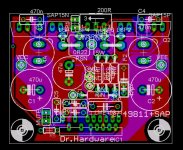
I also have a design for LME49811+STD (or SAP) darlingtons for one year. Its a bit "crowded" but only in 1/8 eurocard (40 x 50 mm). If someone request then I can send the eagle files..
That's very impressive!
Do you have a BOM or any measurements!
Panson,
I know this goes way back in time, but, have you tried the LME49811 without a predriver - reading other posts from Audioman54, he metions that the pre-drivers in the 811 are run Class A hence the limited drive current due to heat limitations of the 811 chip. The pre-drivers in the 810 are run Class A/B for more output current to drive Mosfets. I just finished a driver stage without predrivers using the 811, MJE15032/33 and NJL3281/1302 with the Cordell Thermal Trak bais scheme. Finally got it to work, there is bais current
My rational for doing it without a predrive comes from the idea that a descrete EF scheme should have the same drive capability as a Darlington device and Darlingtons are what National uses to demo the 811 chip.
Just a thought you might want to try.
Ken
Hi Ken,
Congratulations! How much bias current do you use? Is it one pair of NJL?
MJE15032/33 has higher current gain than 15030/31. Its should be fine for not using a pre-driver stage.
Have you measure bias stability/tracking performance against output level?
Panson
Hi Ken,
Congratulations! How much bias current do you use? Is it one pair of NJL?
MJE15032/33 has higher current gain than 15030/31. Its should be fine for not using a pre-driver stage.
Have you measure bias stability/tracking performance against output level?
Panson
Hi Panson,
Thanks. Yes, just one pair, supply voltage is currently 33v. Eventually I will ramp this up.
I'm using the 100mA approx 44mv across the two 0.22 resistors. I haven't measured the stability/tracking yet. I think it is currently under compensated at the bais rises as the temperature increases. I'm going to try different resistor combinations to get it closer, then attempt to measure THD over time.
If you look in the Solid State Forum in the Unique Allison design thread, you'll see that with a lot of help, I've been able to make a Class A amp as well as a Class A that switches to class B above 4watts. All driven by the LME49811. The Allison is a completely different approach to Class A.
Regards,
Ken
LME49811 info
Hi Ken and the rest of the group,
With our simple output stage and VBE multiplier we ran our bias current at about 25ma for the 130W amp at 50VDC rails and 50ma for the 75DC rail amp. We found that with these parts on this vertical process with NPN and PNP transistors that were perfectly matched in terms of carrier flow and dimension (Ft's actually identical!) that the parts measured better at lower bias settings! Not normal I know but after all the measurements showed that was the case we then listened to the amps and found the same thing for sound quality.
Also you are correct that the 811 is a class A output stage and the 810 has an extra class A/B stage added to get more current for higher power amplifiers which was requested by a customer for a 3000 W base guitar amplifier. That is why the 810 part has an actual Baker clamp and a clipping out indicator. the 811 does have a clipping circuit that is not the same circuit as a Baker clamp but I think is just as effective. It was designed by the chip designer. The 811 has no noticeable hang on after coming out of clipping.
The LME49830 was the part that was designed just for FETS.
Several high end stores have heard my amps that I just built that run on 75 volt rails with using the LME49811's and were "Stunned" by the sound quality. Of course I demo'ed them with my LME49713 D/A preamp with the power supplies Bob Pease and I presented at the AES last year so they heard a complete LME signal path with all LME power supply regulator circuits (AND all metal can parts!). Only one type of process sound (error?) in the entire signal path I think makes a big difference instead of inserting parts from 4 different vendors and each one having it's own unique process errors.
Just my 2 cents worth.
Best Regards,
Mark / audioman54
PS – Just hit one year of no job 2 weeks ago! Anyone out there need an over 55 analog / audio applications engineer? Or does anyone want to buy a pair of Krell KSA 200S amps? Don’t need them anymore as the LME49713
kills them!
Hi Mark,
Sorry to hear that you still haven't found anything, my heart goes out to you and your family.
The LME49811 is a pretty versital chip! And robust, I've cooked quite a few transistors while the 49811 was connected and it's still ticking. I'm also enjoying my 48713 pre as well.
Ken
Sorry to hear that you still haven't found anything, my heart goes out to you and your family.
The LME49811 is a pretty versital chip! And robust, I've cooked quite a few transistors while the 49811 was connected and it's still ticking.
I'm also enjoying my 48713 pre as well. Ken
Hi,
if the output stage consists of two gain stages, i.e. driver + output, then the total current gain is good for 8ohm speaker drive from the 811. I reckon the MJE and NJL combination can easily manage the 14Apk that a 100W into 8r0 amp should be able to deliver into a reactive speaker.
Changing to a 4ohm load is rather different. 200W into 4r0 requires a transient current capability of ~28Apk. I believe this can only be achieved with a three stage output, i.e. pre-driver + driver + dual output.
Hi,
if the output stage consists of two gain stages, i.e. driver + output, then the total current gain is good for 8ohm speaker drive from the 811. I reckon the MJE and NJL combination can easily manage the 14Apk that a 100W into 8r0 amp should be able to deliver into a reactive speaker.
Changing to a 4ohm load is rather different. 200W into 4r0 requires a transient current capability of ~28Apk. I believe this can only be achieved with a three stage output, i.e. pre-driver + driver + dual output.
Andrew,
Thanks for the explanation.
Ken
Hi,
if the output stage consists of two gain stages, i.e. driver + output, then the total current gain is good for 8ohm speaker drive from the 811. I reckon the MJE and NJL combination can easily manage the 14Apk that a 100W into 8r0 amp should be able to deliver into a reactive speaker.
Changing to a 4ohm load is rather different. 200W into 4r0 requires a transient current capability of ~28Apk. I believe this can only be achieved with a three stage output, i.e. pre-driver + driver + dual output.
Would 50W into 3 ohm be fine for goint without a pre-driver?
Correction LME49811 not LME49713
Hi Ken and group,
Just wanted to correct the last line of the "PS" in my last post. I meant to say LME49811 (power amplifier preamp) not LME49713 (current feedback opamp)! Just a senior moment slip up. They are both 2 of my favorite parts though along with the LME49710 in applications where VFB parts are a better choice than CFB parts... even though I prefer the sound of the CFB parts.
Mark / audioman54
Mark,
Unless you are going to produce a commercial venture I would really like to see what your final complete layout looks like for a 75+ volt lme49830 mosfet setup.
You do not often get to discuss the product with those who actually worked on the prototype.
I have some of Panson's frontend boards and would like to implement a complete high output version.
Tad
Mark, since you have much more experience than me with this IC, do you have any thoughts about alternate compensation proposed in other thread?
http://www.diyaudio.com/forums/chip...-lme49810-11-thermaltrak-amp.html#post1992974
I intend to build the circuit in a month or two and I am trying to gather as much info as I can if this is . I would begin with Cc=18p (since I like to be on a safe side), Cc2=100p and Rc about 4k7.
Cheers
http://www.diyaudio.com/forums/chip...-lme49810-11-thermaltrak-amp.html#post1992974
I intend to build the circuit in a month or two and I am trying to gather as much info as I can if this is . I would begin with Cc=18p (since I like to be on a safe side), Cc2=100p and Rc about 4k7.
Cheers
That's very impressive!
Do you have a BOM or any measurements!
I have no measurements yet. But if you need the BOM is;
C1 470u
C2 470u
C3 470n
C4 470n
C5 100n
C6 100n
C7 150n
CC 33p (silver)
CC1 47p (silver)
CI 47u
F1 4A
F2 4A
IC1 LME49811
Q1 SAP15N (or STD03N)
Q2 SAP15P (or STD03P)
R1 200R mutiturn trimmer
RB 49K9
RF 49K9
RI 2K
RIN 2K
RS 27K
RSN 0R22 5W
RSP 0R22 5W
Last edited:
Panson:
I notice that you wire all the ThermalTrack diodes in series in your layouts of the boards with multiple pairs of output devices. Of course, the diodes of the NPN should be in series with those in the PNP, but shouldn't the three pairs of transistors have their diodes in parallel in order to get the correct bias voltage? Or am I missing something?
~Tom
- Status
- This old topic is closed. If you want to reopen this topic, contact a moderator using the "Report Post" button.
- Home
- Amplifiers
- Chip Amps
- Comparing LME49810, 49830 and 49811