Re: Re: Re: Hey Freddy...
Thanks Brett, I will look into this thread.
What about the 4015LF, if that is a better driver? I only want F3 of around 35Hz for outdoor PA use.
Thanks again,
Brett said:
Yes, designed and built. Look early in the thread
Thanks Brett, I will look into this thread.
What about the 4015LF, if that is a better driver? I only want F3 of around 35Hz for outdoor PA use.
Thanks again,
| 35 Hz Tapped Horn
Def_Const |Horn Dimensions
{
a1 = 500e-4; |Area at throat (cm^2)
a2 = 881e-4; |Area at rear of driver (cm^2)
a3 = 3100e-4; |Area at front of driver (cm^2)
a4 = 3200e-4; |Area at mouth (cm^2)
l1 = 20e-2; |Distance from throat to rear of driver (cm)
l2 = 250e-2; |Line distance from rear of driver to front of driver (cm)
l3 = 25e-2; |Distance from front of driver to mouth (cm)
}
Def_Driver 'Dr1'
| Eminence Difinimax 4015LF
Sd=873cm2
fs=42Hz
Qes=0.54
Qms=6.73
Vas=116L
Re=5.04
Le=1.49mH
system 'S1'
Driver Def='Dr1' Node=1=0=3=4
Waveguide 'W1' Node=2=3 STh={a1} SMo={a2} Len={l1} Conical
Waveguide 'W2' Node=3=4 STh={a2} SMo={a3} Len={l2} Conical
Horn 'H1' Node=4 STh={a3} SMo={a4} Len={l3} Conical
Two in half space (±2dB 32hz~150hz, 107dB/2.83V/1M)
djk said:
I do not think the idea of a karlson coupler is out of place in this thread. I would indeed be interested in anyone`s comments on the design djk proposed. I had come up with the idea of such a Karlson coupler at the mouth as a way of dealing with two drivers mounted lengthwise along the length of the line near the mouth, instead of a single driver as shown. Imagine a second driver added immediately to the left of the single shown in djk`s drawing. My thoughts/hopes were that the combination of two drivers mounted this way and the addition of the Karlson coupler in lieu of a standard rectangular opening may succeed in obtaining a wider useable passband.
Comments invited.
Re: Re: Re: Re: Hey Freddy...
At current thinking, for the much, much larger room in my home, I'd go with Erik (Volvotreter) design with a 3015LF. See post 666. I have some 3015LF's on the way for my PA, so I can easily build one and try it. I can easily disguise 4 of these in the large room. I've previously built Erik's EVM12L trax and it eas excellent.
Better than what for what size TH? The LAB design earlier isn't optimum, but I have the drivers and it's dimensions are modest, and a pair will be more than enough for my current room.Samuel Jayaraj said:
Thanks Brett, I will look into this thread.
What about the 4015LF, if that is a better driver? I only want F3 of around 35Hz for outdoor PA use.
Thanks again,
At current thinking, for the much, much larger room in my home, I'd go with Erik (Volvotreter) design with a 3015LF. See post 666. I have some 3015LF's on the way for my PA, so I can easily build one and try it. I can easily disguise 4 of these in the large room. I've previously built Erik's EVM12L trax and it eas excellent.
Re: Re: Re: Re: Re: Hey Freddy...
Thanks djk; the 35Hz TH using the 4015LF driver posted by you looks very good. Sorry but I just found out last night that my supplier does not stock 4015LF, but 3015LF is in stock. I guess the TH dimensions will change for the 3015LF for an F3 of 35Hz.
Brett, I meant a better driver for use in a TH as compared to the LAB12 driver.
My intended use is outdoor PA with very high SPLs and a cut off at about 35Hz and not for very low frequency home use.
djk said:| 35 Hz Tapped Horn
Def_Const |Horn Dimensions
{
a1 = 500e-4; |Area at throat (cm^2)
a2 = 881e-4; |Area at rear of driver (cm^2)
a3 = 3100e-4; |Area at front of driver (cm^2)
a4 = 3200e-4; |Area at mouth (cm^2)
l1 = 20e-2; |Distance from throat to rear of driver (cm)
l2 = 250e-2; |Line distance from rear of driver to front of driver (cm)
l3 = 25e-2; |Distance from front of driver to mouth (cm)
}
Def_Driver 'Dr1'
| Eminence Difinimax 4015LF
Sd=873cm2
fs=42Hz
Qes=0.54
Qms=6.73
Vas=116L
Re=5.04
Le=1.49mH
system 'S1'
Driver Def='Dr1' Node=1=0=3=4
Waveguide 'W1' Node=2=3 STh={a1} SMo={a2} Len={l1} Conical
Waveguide 'W2' Node=3=4 STh={a2} SMo={a3} Len={l2} Conical
Horn 'H1' Node=4 STh={a3} SMo={a4} Len={l3} Conical
Two in half space (±2dB 32hz~150hz, 107dB/2.83V/1M)
Brett said:Better than what for what size TH? The LAB design earlier isn't optimum, but I have the drivers and it's dimensions are modest, and a pair will be more than enough for my current room.
At current thinking, for the much, much larger room in my home, I'd go with Erik (Volvotreter) design with a 3015LF. See post 666. I have some 3015LF's on the way for my PA, so I can easily build one and try it. I can easily disguise 4 of these in the large room. I've previously built Erik's EVM12L trax and it eas excellent.
Thanks djk; the 35Hz TH using the 4015LF driver posted by you looks very good. Sorry but I just found out last night that my supplier does not stock 4015LF, but 3015LF is in stock. I guess the TH dimensions will change for the 3015LF for an F3 of 35Hz.
Brett, I meant a better driver for use in a TH as compared to the LAB12 driver.
My intended use is outdoor PA with very high SPLs and a cut off at about 35Hz and not for very low frequency home use.
Def_Driver '3015LF'
Sd=881cm2
fs=42Hz
Qes=0.41
Qms=6.82
Vas=160L
Re=5.31ohm
Le=0.92mH
System 'S1'
Driver 'D1' Def='3015LF' Node=1=0=20=21
Waveguide 'W1' Node=20=21
STh=750cm2 SMo=2200cm2
Vf=10L Len=2.5m T=0.9
Horn 'W2' Node=21
STh=2200cm2 SMo=2444cm2
Len=35cm Conical
System 'S3'
Driver 'D1' Def='3015LF' Node=1=0=20=21
Driver 'D2' Def='3015LF' Node=1=0=20=21
Driver 'D3' Def='3015LF' Node=1=0=20=21
Driver 'D4' Def='3015LF' Node=1=0=20=21
Waveguide 'W1' Node=20=21
STh=3000cm2 SMo=8800cm2
Vf=40L Len=2.5m T=0.9
Horn 'W2' Node=21
STh=8800cm2 SMo=.9776m2
Len=35cm Conical
Four in half space (±1dB 32hz~140hz, 113dB/2.83V/1M), bigger throat, smaller mouth, about the same length. Increasing Vf to 15L brings up the 50hz~60hz region a fraction of a dB, but starts killing the response above 100hz.
Help designing a tapped horn?
hey all. Read through this thread a bit, and i have to say I'm a bit overwhelmed.
I just built a BiB style tapped horn , and i'm pretty happy with it. But I want to try one of these tapped horns for comparison. However, i really am unsure as to where to start.
I'd like to use the same drivers isobarically, just like the horn i just built and have a height of about 7.5 ft.
How do you guys think the two designs would compare?
Any guidance on where to start for a design? Thanks a bunch in advance for any help/guidance
I've been modeling around with Hornresp for 3 days, trying to see if I can "convert" my 2 year old 128L BR (-3dB 30Hz) with a Monacor SPH-212 to a Tapped Horn with the same cutoff and possibly smaller size and better sensitivity.
Reading this whole thread took a couple of days.
I am writing a walktrough about what I learned, but I have a few questions about S2 and L12 that I hope someone can answer.
- The point were the front of the driver comes into the horn is S2, hence it is *there* where we should have 1/2 Sd (for a compression ratio of 2)
Now I noticed that if you decrease the comp ratio (increase S2), you get more output in the middle of the band. I found out that I can make S2 *larger* than Sd and it lowers F3 at the expense of some sensitivity below. As far as I understand there should be a decrease in cone movement by compressing the throat area, but it seems that according to Hornresp one can actually get away with a <1 compression ratio in a TH ??? (Cone movement is actually less than modelled in a TH according to multiple testimonies, so it could be possible ... ???)
- I noticed most designs posted here use about 10cm for L12 and half Sd for S1.
After seeing that S2 is where the driver comes in and there was still a large amount of output above 80Hz, I wanted to have some sort of highpass filter to direct that energy into the passband and gain some output on the upper "knee". Therefore I put an (almost) straight resonator between S1 and S2. To reduce the volume of that resonator further, I decreased S1 and L12, but it would be usefull to have a HP section in the TH Wizard that finds the correct length and taper.
- It is not possible to simulate a compression chamber (see paragraph above) in a TH, but I found out that if you model the BLH the TH Wizard produces (just select No if Hornresp asks if you want to model a TH) and then select Tools>Combined response for 0 cm, it gives an identical SPL curve for the lower frequencies. I therefore think it should be possible - if there is a merit in cutting off/redirecting the HF - to combine a (possibly interacting!) compression chamber and the resonator mentioned above into a HP Section in the TH Wizard. Consider it a feature request Mr. McBean ;-)
- The distance between S3 and S4 can also be increased to get some more output at 80Hz (also in HF section?), but I cant get it to filter higher frequencies unless I reduce the length between S2 and S3.
Hopefully someone can shed a bit more light into this, as it seems almost impossible for me to get a flat response from 30Hz till 80Hz (-3dB).
JSS said:
Greets!
I see while I was away with this #$%^ infection you calc'd a winner.
GM
Hi,
I and a few others are getting sensitivity predictions between 110db and 113db/W/m from the TH model. I used corner loading and an exponential mouth to get 17Hz to 100Hz +-1.5db.
Are these efficiencies really feasible?
If so, then a 10W amplifier will give in excess of 120db/m
I and a few others are getting sensitivity predictions between 110db and 113db/W/m from the TH model. I used corner loading and an exponential mouth to get 17Hz to 100Hz +-1.5db.
Are these efficiencies really feasible?
If so, then a 10W amplifier will give in excess of 120db/m
Probably not, the walls of the horn itself and the room would have to be infinitly rigid and at the same time have infinite damping.
Years ago Burwen built a huge horn loaded hi-fi with four 16" woofers in each bass horn. The horn walls were 4" reinforced concrete. When asked what he would change if he could start over, he replied: use 6" concrete.
Most of the designs I model I do in half space, even then if you're not on the ground floor you will lose low end.
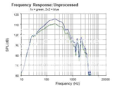
This is an EAW KF940 (stack of four). These are well braced baltic birch double 12 cabinets. In theory a stack of four should get you to 25hz (claimed).
What do you get from going from one to four at 30hz?
Looks like 1dB to me.
Years ago Burwen built a huge horn loaded hi-fi with four 16" woofers in each bass horn. The horn walls were 4" reinforced concrete. When asked what he would change if he could start over, he replied: use 6" concrete.
Most of the designs I model I do in half space, even then if you're not on the ground floor you will lose low end.
This is an EAW KF940 (stack of four). These are well braced baltic birch double 12 cabinets. In theory a stack of four should get you to 25hz (claimed).
What do you get from going from one to four at 30hz?
Looks like 1dB to me.
freddi -
I've been looking at this one: Eminence Deltalite II 2512 Neo 12" Driver
http://www.partsexpress.com/pe/pshowdetl.cfm?&DID=7&Partnumber=290-593&ctab=10#Tabs
It's half the $$$
I've been looking at this one: Eminence Deltalite II 2512 Neo 12" Driver
http://www.partsexpress.com/pe/pshowdetl.cfm?&DID=7&Partnumber=290-593&ctab=10#Tabs
It's half the $$$


judtoff said:Hmm has anyone figured out a suitable
TH for a TB W8 740C? Lol I have one kicking around. I figure its probably been done before. If not I'll design one
I posted one months ago with the MCM 55-2421, which is practically the same driver.
But post yours anyways!
Mine was super-small, and not as efficient as I could have made it.
getting driver values right...
I am wondering if a driver with too high a Bl (magnet strength) is a disadvantage in a TAP horn. Is it possible that with a Bl too high the 1/4 horn cannot as easily manipulate driver values. Looks to me that a Bl in the 9 -11 Tm seems about right. Is this a reasonable assesment?
Further what T/S values account for smooth wide band response of a TAP? It would seem that a Qt in the 0.4 - 0.6 range is good with bass response increasing as the value goes up. Qe, a TAP would seem to like to see a range of 0.3 to 0.6 with the widest BW I have seen on a TAP with a Qe of 0.45. Qm, it has been difficult for me to see any trends but a value of 3.99 was used on the driver which showed very wide BW. Vas as low as possible would seem to be the order of the day, the widest BW I have seen was a driver with a Vas of only 31 litres. Last on my list is Cms and I am not sure what a good range would seem to be so I won't offer any guesses here.
Comment from those with experience would be most welcome. I am interested in what T/S values result in a wide band smooth response TAP horn as opposed to the higest output (gain) TAP.
- Home
- Loudspeakers
- Subwoofers
- Collaborative Tapped horn project